This article covers in-depth details about Errors in Networking, their types, and methods of Error Correction. By the end of this, you will gain a clear understanding of Error Correction in Computer Networking. So, let us dive deep into Error Correction in Networking.
Computer Networks play a crucial role in the secured and encrypted transmission of data over the internet. However, the data transfer over a network includes many complex processes that cause some flaws in the data transmission. These flaws are called Errors which can be of different types. Therefore, it is important to correct them for efficient data transmission.
In this article, we will learn about the different methods of Error Correction in Computer Networks. We will also see the types of errors and methods to identify them. This will resolve all your doubts about the Error Correction and its methods.
What are Errors in Networking?
The error simply means any flaw or deviation that occurs while the information is transmitted from the source to the destination in a computer network. In other words, if the message or data transmitted by the source is not identical to the one received at the destination, we can say that there is some Error in the Computer Network.
In a Network, the data or message is transferred in the form of bits that follow a specific sequence. If there is any deviation in the bit sequence, it is called an Error. Now, let us understand the types of Errors that occur in the Compute Network.
Types of Network Errors
Single-Bit Error
This error occurs when the single bit (single binary digit) in the message is flipped during the transmission and the received message at the destination side differs from the original message by a single bit. For example, if a single 1(set bit) in the source message is flipped to 0 or a 0 is flipped to 1, we can say that there is a Single-Bit Error in Transmission which is shown below:

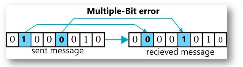
Multiple-Bit Error
This occurs when there is a deviation in multiple bits of the message during its transfer from source to destination. The bits that are flipped need not be a continuous sequence of bits. Thus, a Multiple-Bit Error is found when any non-continuous sequence of bits is flipped in the transmitted message. The example of this error is illustrated below:
Burst Error
This is similar to the Multiple-Bits Error with just one difference the bits that are flipped follow a continuous sequence in their bit representation. This error can occur due a physical damage to the disk which causes a change in the consecutive bit sequence of the source message. An example of a Burst Error is demonstrated below:

After we have learned about the different types of errors, let us see how to identify them so that we can select the appropriate method to correct the Network errors.
Error Identification in Computer Network
Parity Check
In this technique, the sender appends an extra parity bit to the message. If the total number of ones in the bit sequence is odd, 1 is added as a parity bit. And, if it is even, 0 acts as a parity bit. During transmission or storage, if an error alters the number of bits, the parity bit will be used to identify whether there is an error or not. This is illustrated as shown below:

Two-dimensional Parity Check
This is just a variation of the Single-Bit Parity Check in which the original method is transformed into a matrix in which each column is associated with a parity bit based on the number of occurrences of 1s. At the receiving end, if the message has been corrupted in some way, the parity bit can identify that the message is corrupted due to some error. This is illustrated in the below example.

Checksum
This method adds up all the bits and adds the sum to the message while transmitting. This sum is called the checksum. The sender calculates the checksum before transmitting the data, and the recipient recalculates it upon receiving the data. If the two checksum values do not match with each other, there is some error in the network. However, if they match, there is no error. An example of checksum is shown below:

Cyclic Redundancy Check (CRC)
The CRC method is similar to the Checksum method with the difference that this method deals with binary division instead of binary addition. In this method, the repeated or redundant sequence of bits in the source message is identified. Then, it is added to the source message. Now, the source message will be easily divisible by the binary number formed from redundant bits which is called CRC Value.
Thus, the source message is divided by the CRC value which gives the divisor. Before the message is accepted, the receiver divides the bit sequence by the CRC value. If the remainder is zero, there is no error. But, if the remainder after dividing by the CRC value is not zero, it means that there is an error that needs to be corrected. The CRC method is outlined below:

After we have learned to identify the Errors in Computer Networks, it is now time to correct them.
Error Correction in Computer Networks
Once the errors are detected in the network, the deviated bits sequence needs to be replaced with the right bit sequence so that the receiver can accept the data and process it. This method is called Error Correction. We can correct the errors in the Network in two different ways which are listed below:
- Forward Error Correction: In this Error Correction Scenario, the receiving end is responsible for correcting the network error. There is no need for retransmission of the data from the sender’s side.
- Backward Error Correction: Backward Error Correction means that the receiver needs to correct the error either by transmitting the corrupted message or retransmitting the entire message to the destination.
However, there is one of the most widely used Error Correction methods which is called ‘Hamming Code’ which was designed by R.W.Hamming. Let us have a quick look at it.
Hamming Code Error Correction
In this method, extra parity bits are appended to the message which are used by the receiver to correct the single bit error and multiple bit error. Consider the below example to understand this method in a better way.
Suppose the sender wants to transmit the message whose bit representation is ‘1011001.’ In this message:
- Total number of bits(d) = 7
- Total of redundant bits(r) = 4 (This is because the message has four 1’s in it)
- Thus, total bits(d+r) = 7 + 4 = 11
Also, by convention, the redundant bits are always placed in the places which are powers of 2. Now, this message will take the format as shown below:

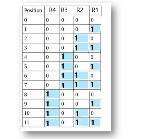
Therefore, we have R1, R2, R3, and R4 as redundant bits which will be calculated according to the following rules:
- R1 includes all the positions whose binary representation has 1 in their least significant bit. Thus, R1 covers positions 1, 3, 5, 7, 9, 11.
- R2 includes all the positions whose binary representation has 1 in the second position from the least significant bit. Thus, R2 covers positions 2,3,6,7,10,11.
- R3 includes all the positions whose binary representation has 1 in the third position from the least significant bit. Hence, R3 covers positions 4, 5, 6, 7.
- R4 includes all the positions whose binary representation has 1 in the fourth position from the least significant bit due to which R4 covers positions 8,9,10,11.
These rules are illustrated below:
Now, we calculate the value of R1, R2, R3 and R4 as follows:
- Since the total number of 1s in all the bit positions corresponding to R1 is an even number. R1 = 0.
- Since the total number of 1s in all the bit positions corresponding to R2 is an odd number, R2= 1.
- Since the total number of 1s in all the bit positions corresponding to R3 is an odd number, R3= 1.
- Since the total number of 1s in all the bit positions corresponding to R4 is even, R4 = 0.
Therefore, the message to be transmitted becomes:

This message is transmitted at the receiver’s end. Suppose, bit 6 becomes corrupted and changes to 0. Then, the message becomes ‘10101101110.’ So, at the receiver’s end, the number of 1’s in the respective bit positions of R1, R2, R3, and R4 is rechecked to correct the corrupted bit. This is done in the following steps: For all the parity bits we will check the
- For R1: bits 1, 3, 5, 7, 9, and 11 are checked. We can see that the number of 1’s in these bit positions is 4(even) so R1 = 0.
- For R2: bits 2,3,6,7,10,11 are checked. You can observe that the number of 1’s in these bit positions is 5(odd) so we get a R2 = 1.
- For R3: bits 4, 5, 6, and 7 are checked. We see that the number of 1’s in these bit positions is 3(odd). Hence, R3 = 1.
- For R8: bits 8,9,10,11 are observed. Here, the number of 1’s in these bit positions is 2 and that’s even so we get R4 = 0.
If we observe the Redundant bits, they give the binary number 0110 whose decimal representation is 6. Thus, bit 6 contains an error. To correct the error the 6th bit is changed from 1 to 0 to correct the error.
Conclusion
Errors are encountered where there is a difference between the sequence of bits of the source message and the received message while data is transferred over the Network. The Errors create a lot of problems in the information transfer by corrupting the data. Thus, the receiver becomes unable to further process the data, due to which the request-response cycle slows down over the network.
After learning about the different methods to correct these errors, we can easily make sure the data transfer doesn’t face any discrepancy or inconsistency. You have received enough information about the Error Correction methods in networking.
Frequently Asked Questions
1. Does Error Correction use additional network bandwidth?
Yes, if the method of Error Correction deals with the retransmission of the packets from the sender’s side, there might be additional usage of network bandwidth that causes an increase in network cost.
2. What is the Redundancy Check method in Error Correction?
A redundancy check simply means adding a certain bit sequence at the end of the message. This added sequence acts as redundant bits and at the receiver’s side, these redundant bits can be checked to verify whether the message transmission is error-free or not.
3. What is Jitter in Networking?
A jitter is another type of network error that is caused by to inconsistent arrival of the data packets at the receiver’s end. Due to this, there is a variation in the arrival time of the message. This error can be observed in voice or audio communication in which the voice or audio is not delivered properly.
4. Does low latency signify a network error?
Low latency means delayed delivery of the data packets. If there is an issue in the network speed for bandwidth, it can be easily rectified. But, if it occurs due to corrupted data or loss of data packets, it can termed as a Network Error.
5. What is the ARQ method?
ARQ is a protocol for backward error correction that automatically detects and requests the retransmission of erroneous packets from the sender’s side. This method asks the sender to resend packets that are corrupted or lost.
Share your thoughts in the comments
Please Login to comment...