Digital circuits are constructed by using different logic gates, so when we use different ICs, we have to produce different logic gates using different technologies. For the fabrication of ICs, we use semiconductor devices-bipolar and unipolar. Based on the devices, digital ICs are made which are then commercially available. When we use a bipolar device, like a transistor in the IC fabrication technology, it is known as bipolar technology. In unipolar technology, we make use of unipolar devices. e.g., MOSFETs. A group of compatible ICs with the same logic level and supply voltages for performing various logic functions which have been fabricated using specified configuration, is referred to as a logic family.
Integrated Circuits
The branch of electronics that deals with the research, development, and utilization of qualitatively new electronic devices is known as integrated microcircuits. This is the semiconductor based chip which consist of set of digital circuitry.
Integrated microcircuits generally known as integrated circuits a low-cost electronic circuits consisting of active and passive components that are joined together on a single crystal chip of silicon. These interconnected components that make an IC are called integrated circuit elements. In Digital ICs, information is represented by binary digits, e.g. microprocessors, etc.
Classification of Digital ICs
The classification is based on the complexity of the circuit:
Bipolar ICs
The main elements of a bipolar IC are diodes and transistors. In this classification, they are further divided into two types based on the BJT (Bipolar junction transistor) operating mode.
- Saturated Mode: In saturated logic, the transistors are driven to saturation mode, the saturated bipolar ICs are: Resistor-Transistor Logic (RTL), Diode Transistor Logic (DTL), Direct Coupled Transistor Logic (DCTL), High Threshold Logic (HTL), Transistor -Transistor Logic (TTL), Integrated Injection Logic(I2L).
- Non-saturated Mode: The non-saturated bipolar ICs are: Schottky TTL, Emitter Coupled Logic (ECL)
Unipolar ICs
MOS devices are unipolar devices and only MOSFETs are employed in these MOS logic circuits. The MOS logic families are PMOS, NMOS, and CMOS.
Characteristics of Digital ICs
On moving towards the characteristics – they are temperature sensitive in nature and the rest other are Some important characteristics or parameters are given as follows:
- Speed of Operation
- Power dissipation
- Figure of merit
- Fan Out
- Fan In
- Current and voltage parameter
- Noise Immunity
- Operating temperature range
- Discrete Signal Level
- Storage
Speed of Operation
The speed of a digital circuit is expressed in terms of propagation delay. The input and output waveforms are shown in Fig.1(a) and Fig.1(b). The delay times are measured between the 50% voltage levels of input and output.Fig.1(a) shows that when we apply an input to a logic gate, output occurs after some time i.e. propagation delay.Fig.1(b) shows the input and output waveform.

Speed-of-operation-(a)
The two propagation delay times are defined as follows:
- tPLH: It is the propagation delay time in going from logical LOW (0 state) to logical HIGH (1 state)
- tPHL: It is the propagation delay time in going from logical HIGH (1 state) to logical LOW (0 state)

Speed-of-operation-(b)
Power Dissipation
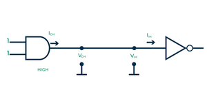
Any digital circuit requires some power for operation. This is the amount of power dissipated in an IC. It is determined by the current an IC draws from the VCC supply, it is expressed by VCC ✖ ICC. This power is specified in milliwatts.
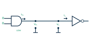
It is shown in Fig.2 that when the gate is in the HIGH output as shown in Fig.2(a), the current drawn by the gate is represented by ICCH. Similarly, in the LOW output, the current drawn by ICCL is in Fig.2(b).

Power-dissipation-(a)
The power of the circuit is the product of the supply voltage and current drawn by the circuit when the input is applied to the gate as shown in Fig.2, the output changes between logic 1 and logic 0 which means the supply current changes between ICCH and ICCL. So the average current drawn by the circuit will be
ICC (avg) = (ICCH+ICCL)/2
We take the average of both currents because the power dissipation depends on the duty cycle and is generally specified for a duty cycle of 50%. So, the average power dissipation of the circuit is
P(avg) = VCC ✖ ICC(avg)
P(avg) = VCC ✖ [(ICCH + ICCL)/2]
If an IC has four gates, then the power dissipated will be four times the power dissipated by each gate.

Power-dissipation-(b)
Figure Of Merit
The figure of merit is defined as the product of speed and power. The speed of the logic circuit is specified in terms of propagation delay, so the figure of merit is specified in milliwatts.
Figure of merit = propagation delay ✖ power
Fan Out
Fanout is the maximum number of similar logic gates that a gate can drive without any degrading in voltage levels. High fanout is advantageous because the need for additional drivers to drive more gates is less. It is used to derive the logical inputs for the working and it means the maximum number of standard logic inputs which an be derive efficiently.
Fan In
It is defined as the number of inputs that can be connected to a gate. For example, 7400 represents two input NAND gates, therefore fan-in of 7400 is 2. So it is basically the number of input it can handle properly for the procedure or working.
Current and Voltage Parameter
Current and voltage parameters are very important in designing a digital system.Fig.3(a) and Fig.3(b) show the current and voltage in the two logic gates.
Current-and-Voltage-Parameter-(a)
- VIH(min) – High-level input voltage: It is the minimum voltage level required for logic 1 as an input. Below this minimum level, it will not be accepted as a HIGH by the logic circuit.
- VIL(max) – Low-level input voltage: It is the maximum voltage level required for logic 0 at an input. Any voltage above this level will be considered as a HIGH input.
- IOL(max) – Low-level output current: It is the maximum current level at a logic circuit output in the logical 0 state under the defined load condition.
- IIH(min) – High-level input current : It is the current that flows into an input when a specified high-level voltage is applied to that input.
- IIL(max) – Low-level input current
It is the current that flows into an input when a specified low-level voltage is applied to that input.
- IOL – High-level output level current
It is the current that flows from output in the logic 1 state under specified load conditions.
- IOL – Low-level output current
It is the current that flows from an output in the logic 0 state under specified load conditions.
Current-and-Voltage-Parameter-(b)
Noise Immunity
The input and output levels of a digital circuit are specified by a voltage level.Fig.4 shows the input and output voltage levels. Some unwanted voltage might be induced due to electric and magnetic field, known as noise. This may cause the voltage at the input of a logic circuit to drop below VIH or rise above VIL and may produce undesired operation. Noise immunity is the maximum noise voltage that may appear at the input of a logic gate without changing the logical state of its input.

Input-Output-Voltage Levels for Noise Community
State 1 noise margin – VOH – VIH
State 0 noise margin – VIL – VOL
Operating Temperature
All IC gates are semiconductor devices. They are temperature-sensitive by nature. The operating temperature ranges of an IC vary from 0℃ to + 70℃ for consumer and industrial applications, temperature ranges from -55℃ to +125℃ for military applications.
Discrete Signal Level
The digital circuits works on this property also which have only two values to represent the low and high voltage level: in binary terms we say it- 0 and 1. This feature helps to process the correct form of data and represent it accurately so we can say that the characteristics of the discrete signal level helps the digital circuit to improve its efficiency.
Storage
In order to store the data, a variety of components have been used by the digital circuits ,these components are based on the short term and long term storage also in which we can include the example of the flip flop, register , RAM , flash memory ,etc. The storage components depend that how much space is needed for the data to set and accordingly the component is used for that , so for both short and long term storage areas are available in digital ICs.
Features of ICs
- An IC perform complex functions. Example: a single transistor cannot amplify signal voltage, whereas an IC perform function of amplification.
- Reliability and cost are not affected by an increase in complexity of ICs.
- In an IC, the adjacent components are spaced mostly 50-100 micrometer apart.
- In an IC, interconnection of individual elements is made through metallization (i.e. without soldering and welding)
Advantages of ICs
- Low cost and extremely small size due to fabrication of various circuit elements in a single chip.
- Low power consumption.
- Increased system stability due to elimination of soldered joints.
- Lesser weight and space requirements.
Disadvantages of ICs
- If any component in an IC goes out of order, then the whole IC has to be replaced by new one.
- For high power production, an IC is not used.
- There is lack of flexibility in an IC.
- It is not possible to fabricate inductors and transformers.
Applications of Digital ICs
Integrated circuits are used in different forms with different shapes and sizes. The uses of the integrated circuit include:
- Radar
- Wristwatches
- Computers
- Video Processor
- Logic devices
- Memory devices
- Audio amplifiers
- Microwave amplifiers
- Small signal amplifiers
- Radiofrequency decoders and encoders
- Voltage regulators
- Timers
- Clock chips
- Flip flops
- Memory chips
- Counters
- Temperature Sensors
- Microcontrollers
Conclusion
Integrated circuits are among the most important inventions of the 20th century. They have revolutionized nearly every industry, and there’s no end in sight. In fact, it’s likely that we will see more and more uses of the ICs as time goes on. Integrated circuits have changed our world in countless ways. They have made our lives easier, more efficient, and more connected than they ever were before. And they continue to do so.
Integrated circuits have become an essential tool for electrical engineers working with applications as diverse as consumer electronics, aerospace systems, and medical equipment. ICs offer many benefits, including small size, low cost, and increased reliability, some drawbacks are associated with their use, such as complexity, vulnerability to damage, and security concerns.
FAQs on ICs
What components do digital ICs contain?
A single IC could contain thousands or millions of:
- transistors
- resistors
- capacitors
- diodes
Elaborate the term unit load.
Fanout is specified in terms of unit loads. A unit load for a logic gate equals one input to a similar circuit. For example, a unit load for a 7400 NAND gate equals one input to another logic in the standard 7400 series (not necessarily a NAND gate).
Unit loads (Fan out) = IOH / IIH = IOL / IIL = 400 ????A/40????A = 16 mA/1.6 mA
A standard 74 series TTC gate can drive 10 unit loads. Most of the other TTL series, such as the LS can drive 20 unit loads.
What is the difference between an analog IC and Digital IC?
- Analog ICs accept and output analog data through its pins whereas digital ICs deal with only logic data inputs and outputs.
- Almost every analog IC requires external components for its functioning whereas digital ICs don’t require external components.
- Ex. IC555 is analog IC and trigger pin is given variable input which is accepted by IC for dedicated application. On other hand, digital IC like 7404 which is a NOT gate with TTL logic level works only in voltage range of 0–0.8V and 2–5V only.
What is propagation delay?
Propagation delay is defined as the time taken for the output of a gate to change after the inputs have changed.
What are the functions of integrated circuits?
A tiny chip known as an integrated circuit serves as a microprocessor, oscillator, amplifier, or computer memory.
Share your thoughts in the comments
Please Login to comment...