In the world of electrical engineering power conversion plays a very important role in efficiently managing energy flow across various electronic systems. Among the types of conversion techniques, the boost converter plays a very important role in voltage regulation. It is one of the simplest types of switch mode converter With its ability to step up DC voltage levels, it finds extensive useful in diverse applications ranging from portable electronics to renewable energy systems.
What is a Boost Converter?
A boost converter is an electronic circuit that increases the input voltage from the source to give a high output voltage. It is commonly used in many devices to efficiently step up voltage levels like in electronics that run on battery or renewable energy systems.
The boost converter is used to “step up” an input voltage to a higher level, required by a load. This unique capability is achieved by storing energy in an inductor and releasing it to the load at a higher voltage. By effectively manipulating the timing and duty cycle of the switching operation, boost converters can efficiently regulate the output voltage across a wide range of input voltages and load conditions.
Additionally, various control techniques, such as pulse-width modulation (PWM), are Used to ensure stable and reliable operation, making boost converters Important in modern electronic systems.
Boost Converter Operating Principle
The working of the Boost converter can be explained in two modes of operation :
- Switch is ON and the Diode is OFF
- Switch is OFF and Diode is ON
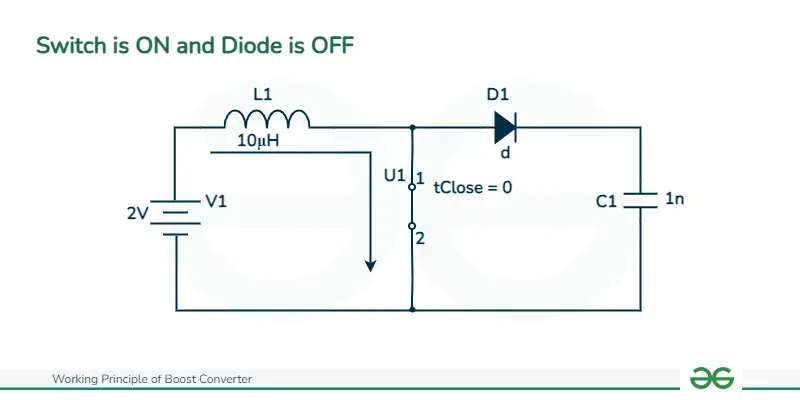
Switch is ON and the Diode is OFF
During this mode of operation in a boost converter, the circuit will transfer energy from the input source to the output of the load. When the switch, typically a MOSFET, is turned on, the input voltage charges the inductor, which causes it to store energy in the form of a magnetic field. During this time the output capacitor will supply power to the load to maintain a stable output voltage. The capacitor will get charged during this time since it cannot discharge through the reversed baised diode. The switch plays a important role in controlling the current flow through the circuit and switching on the regulation of the output voltage through signals. Efficient regulation ensures that the boost converter can maintain a constant output voltage despite variations or changes in the input voltage which contributes performance and its reliability.
Hence this working mode makes the boost converter efficiency in stepping up voltage levels. By effectively transferring of energy from the input source to the output load it minimizes power losses and checks that there is a continuous and proper power supply. Stability and reliability are very important which requires proper voltage regulation and transient response to store dynamic load changes. By understanding this mode of operation we come to know the role of boost converter in various applications from battery powered devices to renewable energy systems where maintaining proper voltage levels is very important for optimal performance.
Change in current([Tex]\Delta Il[/Tex])
When the switch is on the inductor is charged due to the input voltage. The change in current through the inductor during this phase can be derived using the relationship between voltage and current and inductance :
[Tex]V=L.di/dt[/Tex]
Rearranging the above equation we can write as :
[Tex]\Delta Il=V.dt/L[/Tex]
when switch is on the voltage across the inductor is equal to input voltage hence we can write V as :
[Tex]V = Vin[/Tex]
The change in time dt when switch is on the duty cycle is multiplied by the switching period can be written as :
[Tex]dt = D . T[/Tex]
L = inductance of inductor
Substituting these values into the equation :
[Tex]\Delta Il = Vin*D*T/L [/Tex]
change in current ([Tex]\Delta Il[/Tex]) through the circuit is
[Tex]\Delta Il = Vin*D*T/L [/Tex]
[Tex]\Delta Il = [/Tex][Tex]2V*0.71*10\mu s/10\mu H[/Tex]
[Tex]\Delta Il=1.4A[/Tex]
Where :
Vin is the input voltage = 2V
D is the duty cycle of the switch ([Tex]D=Vout/Vin+Vout[/Tex]) = 0.71
T is the period of the switching cycle([Tex]T=1/F[/Tex]) = [Tex]10\mu s[/Tex]
L is the inductance of the inductor = [Tex]10\mu H[/Tex]
Switch is ON and Diode is OFF
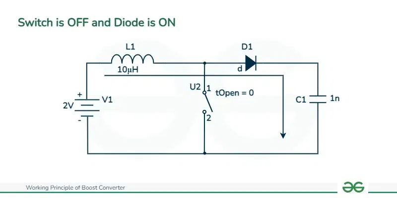
Switch is OFF and Diode is ON
During this mode of boost converter operation the input is off as the switch is turned off. In this state the inductor was storing energy before and now it will serve as an energy source. As there will be no magnetic field present, it will start inducing a voltage in the opposite direction, effectively boosting the output voltage. This induced voltage will allow energy to flow through the diode and into the output capacitor and the load which ensures a stable output voltage and a continuous supply of power to the load. This phase is very important for maintaining stable operation of boost converter ensuring that a smooth power supply even when there is no input source is available.
Hence this operational mode shows us the ability of boost converter to efficiently manage stored energy into the inductor and maintain a constant output voltage. The boost converter makes sure that a stable and reliable power supply to many applications which includes such as battery-powered devices and renewable energy systems. Understanding this mode shows us the mechanisms behind the boost converter functionality and its role in giving stable voltage levels.
In this mode the inductor will discharge its stored energy from the output load and this output voltage is applied across the inductor. This change in current through the inductor in this mode is derived using the same relationship between voltage and current and inductance
[Tex]V=L.di/dt[/Tex]
V is the voltage across the inductor
L is the inductance of the inductor
[Tex]di/dt[/Tex] is the rate of change of current through the inductor
rearranging the above equation we can write as :
[Tex]\Delta Il=V.dt/L[/Tex]
where dt is change in time when switch is on the voltage across the inductor is equal to the input voltage (Vin) and when switch is off the voltage across the inductor is equal to the output voltage (Vout)
so V can be expressed as :
[Tex]V = Vout – Vin[/Tex]
also change is time dt is equal to switching period multiplied by duty cycle complement (1 – D) so we can write dt as
[Tex]dt = (1-D).T[/Tex]
L = inductance of inductor
Substituting these values into the equation :
[Tex]\Delta Il=(Vout−Vin)⋅(1−D)⋅T/L[/Tex]
change in current ([Tex]\Delta Il[/Tex]) through the circuit is
[Tex]\Delta Il=(Vout−Vin)⋅(1−D)⋅T/L
[/Tex]
[Tex]\Delta Il= 3V*0.29*10\mu s/10\mu H[/Tex]
[Tex]\Delta Il=0.87V*10\mu s/10\mu H[/Tex]
[Tex]\Delta Il=0.87A[/Tex]
where
Vin is the input voltage = 2V
Vout is output voltage = 5V
D is the duty cycle of the switch ([Tex]D=Vout/Vin+Vout[/Tex])= 0.71
T is the period of the switching cycle([Tex]T=1/F[/Tex]) = [Tex]10\mu s[/Tex]
L is the inductance of the inductor = [Tex]10\mu H[/Tex]
Switch is OFF and Diode is ON
Given below is the output waveform
.webp)
Waveform representation
In the above output waveforms we have got two time periods Ton and Toff. Ton is the time period at which the transistor is turned ON and Toff is at which the transistor is turned OFF. We can see that during the Ton period the transistor output voltage Vo will be zero IL will start to increase from Imin to Imax and the diode current will be zero.
The equation is given below :
[Tex]VL-Vo + Vin = 0[/Tex]
[Tex]VL = Vo -Vin[/Tex]
Now the energy supplied to the inductor during the start period of transistor is given as
Won = Voltage across inductor × Average current through the inductor × Ton
[Tex]Won = Vin (Imin + Imax/2) Ton[/Tex]
during the OFF period of transistor the energy supplied by the inductor is given as
Woff = Voltage across inductor × Average current through the inductor × Toff
[Tex]Woff = Vo -Vin(imin + imax/2) Toff[/Tex]
therefore Won = Woff
[Tex]Vin(Imin + Imax/2)Ton=Vo-Vin(Imin + Imax/2)Toff[/Tex]
[Tex]VinTo=VoToff – VinToff[/Tex]
[Tex]VoToff = Vin(Ton + Toff)[/Tex]
We know that [Tex]T = TON + TOFF[/Tex],
[Tex]VoToff = VinT[/Tex]
[Tex]Vo = Vin T/Toff[/Tex]
[Tex]Vo = Vin (T/T – Ton)[/Tex]
[Tex]Vo = Vin(T/T – Ton/T)[/Tex]
[Tex]Vo = Vin(1/1 -\alpha)[/Tex]
Applications of Boost Converter
Boost converters find application in various fields
- It is used in devices which are battery powered.
- It is used in renewable energy systems such as solar panels etc.
- It is used in automotive electronics industries.
- It is also used in Wireless Communication to communicate wirelessly.
- It is used to regulate power system.
- It is used to easily adapt control applications
- It is used electronics based consumer
- It is used in circuits for power factor correction.
- It is used in heating and welding machinery.
Advantages of Boost Converter
- It efficiently step-ups voltage capabilities.
- It is Compact in size and is also lightweight to handle.
- They have high flexibility.
- They are cost effective.
Disadvantages of Boost Converter
- Boost converters are more complex to design compared to other voltage regulators.
- During rapid switching they generate electromagnetic interference and switching noise.
- Due to switching action they produce output ripple.
- During switching they produce voltage spikes.
Conclusion
At last the boost converter shows its ability to efficiently step up voltage levels to meet the requirements of various electronic system. The boost converter makes sure that there is a stable output voltage regulation which is essential for powering a variety of electronic devices. This makes us understand the importance of boost converters in modern electronics which enables stable and reliable power supply solutions for battery powered devices and renewable energy systems and automotive electronics. Despite its complexity, understanding the working principles of the boost converter is very important for design and implementation of efficient voltage regulation circuits in wide range of applications.
Working Principle of Boost Converter – FAQs
Can a boost converter be used for voltage down conversion ?
boost converters are mainly used for stepping up voltage but boost converter can facilitate both step-up and step-down voltage conversions.
How does the efficiency of a boost converter changes with load conditions ?
The efficiency of a boost converter increases at medium load conditions and may decrease at light or heavy loads due to factors like losses due to switching actions and mismatching of components etc.
Are there any rules for safety when designing with boost converters ?
Yes there are safety measures such as input or output voltage limitations high current protection etc to ensure safe operation of circuits especially in high-power applications.
Share your thoughts in the comments
Please Login to comment...