Structure of Circuit Switches
Last Updated :
16 Oct, 2023
Circuit switches are a form of telecom switch that creates a dedicated circuit between two endpoints for the duration of a communication session. This dedicated circuit ensures that the connection remains constant and uninterrupted throughout the entire conversation or data transfer.
Switching refers to the transmission of data along channels in order to transmit it from the originator to the receiver. Circuit switching is a switching process that transmits data from source to destination through a specific communication channel. During the connection, the path and resources for the circuit are reserved.
Circuit Switching Network Phases
Phase 1: Circuit Establishment
- In this phase, a dedicated circuit is established between the source and the destination through different intermediate switches.
Phase 2: Data Transfer
- Now in this phase when the circuit is connected, the sender starts to send the data to the receiver.
Phase 3: Termination
- When the data is completely transferred between the sender and receiver the connection is terminated. Then all the nodes involved in the connection are informed to release the resources that were reserved for the circuit.
Steps for Circuit Switching Network Phases
Below mentioned are the steps that are required for Circuit Switching Network Switches
Step 1: Let us take an example that the node 2 wants to communicate with node 3.

Step 1
Step 2: Now in step 2 dedicated path is established between node 2 and node 3.

Step 2
Step 3: As shown in below figure 3 Data is transferred along the reserved path.

Step 3
Step 4: After the data is transferred between node 2 and node 3 Now the connection will be terminated and the reserved resources are returned.

Step 4
Structure of Circuit Switches
Circuit switching uses either of the two technologies:
A. Space-Division Switch
In space-division switching the paths in the circuit are separated from one another spatially. Although it was initially intended for analog networks, this technology is now used in both analog and digital networks.It has evolved through a long history of multiple designs.
B. Crossbar Switch
- A crossbar switch connects n inputs to m outputs in a grid, using electronic microswitches or transistors at each crosspoint as shown in figure 5 below.
- The main problem with this design is that it needs too many crosspoints.To connect n inputs to m outputs using a crossbar switch it requires n x m crosspoints.
- Now if we take an example connecting 1000 inputs to 1000 outputs requires a switch with 1,000,000 crosspoints. A crossbar with this number of crosspoints is impossible.
- Such a switch is also inefficient because statistics show that, in practice, fewer than 25 percent of the crosspoints are in use at any given time. The rest are idle.
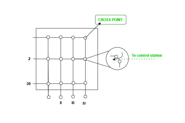
Figure 5: Crossbar Switch with three inputs and four outputs
C. Multistage Switch
- The solution to the limitations of the crossbar switch is the multistage switch, which combines crossbar switches in different (normally three) stages, as shown in Figure 6 below.
- In a single crossbar switch, only one row or column (one path) is active for any connection. So we need N x N crosspoints. If we can allow multiple paths inside the switch, we can decrease the number of crosspoints.
- Each crosspoint in the middle stage can be accessed by multiple crosspoints in the first or third stage.
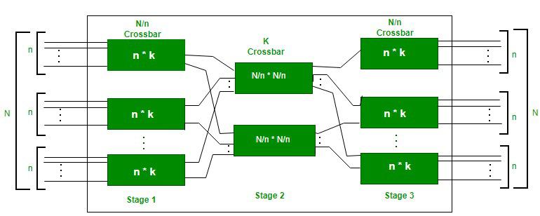
Figure 6: Multistage switch
Steps To Design a Three-Stage Switch
Step 1: We divide the N input lines into groups, each of n lines. For each group, we use one crossbar of size n x k, where k is the number of crossbars in the middle stage. In other words, the first stage has N/n crossbars of n x k crosspoints.
Step 2: We use k crossbars, each of size (N/n) x (N/n) in the middle stage.
Step 3: We use N/n crossbars, each of size k x n at the third stage.
To calculate the total number of crosspoints for that we have given formula as shown below:
N/n (n ✳ k) + k(N/n ✳ N/n) + N/n (k ✳ n)
= 2kN + k (N/n)2
In a three stage switch the total number of crosspoints is
2kN + k (N/n)2
Which is much smaller than the number of crosspoints in a single stage switch N2
Time-Division Switch
- Time-division switching uses time-division multiplexing (TDM) inside a switch.
- The most popular technology is called the time-slot interchange (TSI).
Time-Slot Interchange Figure 7 shows a system connecting four input lines to four output lines. Imagine that each input line wants to send data to an output line according to the following pattern:

Figure 7: Time-slot interchange
- The figure combines a TDM multiplexer, a TDM demultiplexer, and a TSI consisting of random access memory (RAM) with various memory locations.
- The size of each location is the same as the size of a single time slot. The number of locations is the same as the number of inputs (in most cases, the numbers of inputs and outputs are equal).
- The RAM fills up incoming data from time slots in the order received. Slots are then sent out in an order based on the decisions of a control unit.
Time and Space-Division Switch Combinations
- When we look at space-division switching and time-division switching side by side, we can see some interesting facts.
- The advantage of space-division switching is that it is instantaneous.
- Its disadvantage is the number of crosspoints required to make space-division switching acceptable in terms of blocking.
- The advantage of time-division switching is that it needs no crosspoints.
- Its disadvantage, in the case of TSI, is that processing each connection creates delays.
- Each time slot must be stored by the RAM, then retrieved and passed on.
- In a third option, we combine space-division and time-division technologies to take advantage of the best of both.
- Combining the two results in switches that are optimized both physically (the number of crosspoints) and temporally (the amount of delay).
- Multistage switches of this sort can be designed as time-space-time (TST) switch.
- Figure 8 shows a simple TST switch that consists of two time stages and one space stage and has 12 inputs and 12 outputs.
- Instead of one time-division switch, it divides the inputs into three groups (of four inputs each) and directs them to three timeslot interchanges.
- The result is that the average delay is one-third of what would result from using one time-slot interchange to handle all 12 inputs. The last stage is a mirror image of the first stage.
- The middle stage is a spacedivision switch (crossbar) that connects the TSI groups to allow connectivity between all possible input and output pairs (e.g., to connect input 3 of the first group to output 7 of the second group).

Figure 8: Time-space-Time Switch
Frequently Asked Questions
Q.1: What is the basic structure of a circuit switch?
Answer:
The basic structure of a basic circuit switch typically consists of the following elements:
i. Line Interface:
- This interface connects the circuit switch to the incoming and outgoing communication lines.
- It regulates both the physical connection and signaling between the switch and external devices.
ii. Switching Matrix:
- The switching matrix, a crucial component, enables the capability to direct incoming calls to the appropriate outbound lines.
- It allows for the construction of specialized circuits between calling and receiving parties.
iii. Control Unit:
- The control device monitors the use of the circuit switch.
- It monitors the availability of resources, controls the switching matrix, and manages call setup and deconstruction.
iv. Signaling System:
- Signaling enables switch-to-switch call setup, teardown, and other control functions. It ensures configuration and release of the circuit.
Q.2: How does the switching matrix function in a circuit switch?
Answer:
- It is the responsibility of the switching matrix to route incoming calls to the appropriate outgoing lines.
- It comprises of a collection of crosspoints where incoming and outgoing lines meet. When a call is initiated, the switching matrix dynamically creates a dedicated path between the sender and the recipient by closing the appropriate crosspoints.
Q.3: Are there different types of circuit switch?
Answer:
Yes, there are different types of circuit switches designed for specific applications. Some common types include:
- Public Switched Telephone Network (PSTN) Switches.
- Private Branch Exchange (PBX).
- Time-Division Multiplexing (TDM) Switches.
- Digital Circuit Switches
- Carrier Switches
Q.4: Is circuit switching still used today?
Answer:
- Despite the fact that circuit switching is less prevalent in modern communications, it is still used in certain circumstances.
- Traditional landline telephone networks, for example, frequently employ circuit switching. Nevertheless, many telecommunications networks have migrated to packet switching, which is more efficient for data transmission and can support multiple services over the same infrastructure.
Share your thoughts in the comments
Please Login to comment...