In power electronics, a chopper refers to a type of electronic switch that is used to control the flow of electrical power. It functions as a high-speed ON/OFF semiconductor switch that modulates the voltage or current in a circuit. A chopper is a static device that transforms a fixed DC input voltage into a variable DC output voltage. It acts as the DC counterpart(equivalent) of an AC transformer due to its similar behavior. These are also used in trolley cars, marine hoists, forklift trucks, and mine haulers. Future electric automobiles are likely to use choppers for their speed control and braking. The chopper system offers smooth control, high efficiency, fast response, and regeneration.
What is Chopper?
Choppers are commonly employed in DC-to-DC converter circuits to regulate the output voltage or current. As choppers involve one-stage conversion, these are more efficient. Choppers are now being used all over the world for rapid transit systems. A chopper is a high-speed on/off semiconductor switch. It connects the source to the load and disconnects the load from the source at a fast speed.
The primary function of a chopper is to chop or interrupt the output power, resulting in a pulsated output. By adjusting the duty cycle (ratio of on-time to total cycle time) of the chopper, the effective voltage or current delivered to the load can be controlled. This makes choppers a versatile tool for power control and conversion in various applications, including motor devices, power supplies, and renewable energy systems.
Classification of Chopper
Choppers are often classified based on their operating modes, such as :
- Step Up Chopper
- Step Down Chopper
- Step Up/Down Chopper
What is a Step-Down Chopper(Buck Converter)?
A step-down chopper also known as a buck converter, is an electronic circuit used to regulate and reduce the voltage level in a direct current electrical system. It operates by rapidly switching a semiconductor device, typically a transistor, to control the energy flow. By adjusting the duty cycle of the switching process, the chopper efficiently converts a higher input voltage to lower output voltage . Step down choppers find the applications in various power supply systems , where the need for voltage regulation and reduction is essential for powering electronic devices efficiently .
A Step-down chopper is a high-speed semiconductor switch ,utilizing components like power BJT , power MOSFET , transistor , or SCR based on voltage ,current and switching rate needs . A chopper whose average DC output voltage is less than the source voltage is called a step-down chopper . It is also known as buck chopper .It operates by rapidly switching the input voltage on and off to achieve the desired output voltage.
The operation of a step-down chopper involves controlling the duty cycle of the switching device .The duty cycle represents the fraction of time the switch is in the ON state compared to the total switching period. By adjusting the duty cycle ,the average output voltage can be effectively regulated.
Construction and Components of Step-Down Chopper
A step-down chopper consists of a switching device controlling energy flow from a higher input voltage . An inductor connected in series to stores energy during on time , and a freewheeling diode ensures continuous current flow during off time . A capacitor in parallel with the load filters output voltage ripples. The control circuit regulates the switching device’s duty cycle , employing techniques like pulse width modulation . A feedback system may monitor and stabilize the output voltage .The load receives the stepped down voltage , completing the construction of this efficient DC-DC converter used in power electronics applications.
- Input source : The input source provides the higher voltage that needs to be stepped down . This can be an unregulated DC source or rectified AC source , depending on the application.
- Switching device : The heart of the step down chopper is an switching device , often a semiconductor device like MOSFET or an IGBT . The switching device is responsible for controlling the flow of current through the circuit .
- Inductor : An inductor is connected in series with the load and helps store energy during the on time of the switching device . The inductor smoothens the current and plays a crucial role in the energy transfer process.
- Diode : A freewheeling diode connected in parallel with the load to provide a path for the inductor current when the switching device is turned off .This diode allows the inductor current to continue flowing in the same direction , preventing damage to the circuit and ensuring continuous power flow to the load.
- Capacitor : A capacitor often connected in parallel with the load to filter out any remaining ripples in the output voltage .It helps in stabilize the output voltage and improves overall performance of the chopper .
- Load : The load is the device or system that receives the stepped down voltage . It could be a motor , electronic device , or any other component that requires a lower voltage.
Working of Step-Down Chopper with R Load
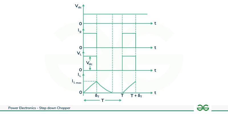
The circuit configuration depicts a step-down chopper connected to a resistive load with a fixed DC supply . In this circuit ,the chopper is situated between the resistive load and the source, receives power from the fixed DC supply and delivers stepped-down DC output to the load . When the chopper is switched ON , the load becomes part of the circuit , and the load voltage (VL) mirrors the source voltage(Vdc) i.e..
VL=Vdc
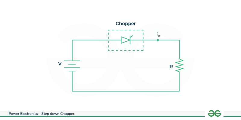
Step Down Chopper with R load
During the chopper’s ON state (from time t=0 to δT) ,the load voltage VL equals the source voltage Vdc , and the load current IL aligns with the load voltage. At t= δT , when the chopper switches OFF , both load voltage and load current drop to zero. Given the resistive nature of the load, the load current mirrors the load voltage but with a reduced magnitude.
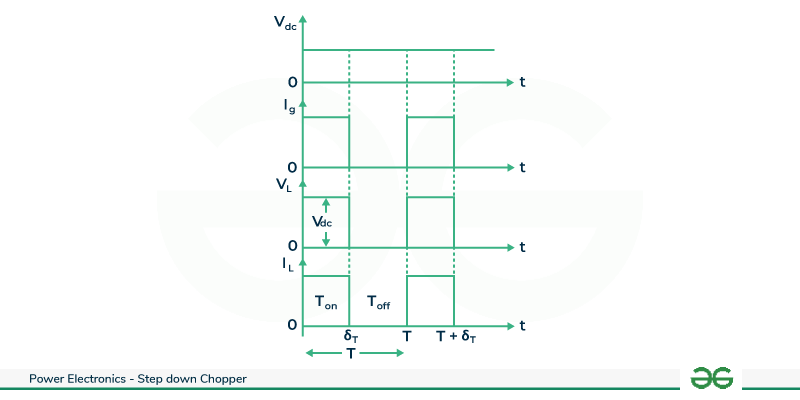
Voltage and Current Waveform
This is a cyclic process repeats as the chopper is turned ON again at t=T. The ON duration , δT determines the output characteristics, offering control over the average load voltage .This step-down chopper configuration proves vital in applications such as power supplies and motor control , enabling efficient regulation of voltage for diverse electronic systems .
Working of Step-Down Chopper with RL Load
The circuit configuration depicts a step down chopper connected to a RL load with a fixed DC supply. Choppers are commonly employed to drive separately excited DC motors, where the motor’s armature is modeled as an RL-load , combining resistance and inductance in the context of a step-down chopper , two modes for the load current are possible due to the interaction of the chopper with the RL-load . They are:
- Continuous load current
- Discontinues load current
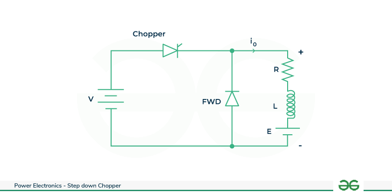
Step Down Chopper with RL Load
Continuous Load Current Mode
In the scenario of a high load inductance ,continuous load current is achieved in a step-down chopper system. During the chopper’s ON period (0 to δT) , the RL load connects to the circuit , causing the load voltage (VL) to track the source voltage(Vdc) , and load current rises to its maximum at t= δT. When the chopper switches OFF( δT to T), load voltage drops to zero, but the load current persists due to the load inductance , preventing sudden current changes . Thus once the chopper is turned OFF , the stored current in the load inductance freewheels through the free-wheeling diode D f , gradually decreasing to its lower limit as depicted in the waveforms.
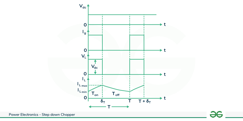
Voltage and Current Waveform
Discontinues Load Current Mode
When the load inductance is small in a step-down chopper system , discontinuous load current results . During the chopper OFF period , the load voltage drops to zero and the load current starts decreasing . Subsequently , the load current reaches zero at a specific moment and stays at zero until the chopper is turned ON again(t=T) . This pattern repeats, creating a waveform for the load current that exhibits discontinuity . The small load inductance allows for a more rapid decrease in current during the OFF period , leading to the intermittent nature of the load current in this configuration.
Voltage and Current Waveform
Derivation of Average Output Voltage
From the waveforms , we can see that the load voltage flows only during the turn ON period(Ton) of the chopper .The average output voltage is given by ,
When switch is closed, diode is reverse biased and supply voltage will charge the inductor.
Vdc = Average value of output or load voltage.
I dc = Average value of output or load current.
ton =Time interval for which SCR conducts.
toff =Time interval for which SCR is OFF.
T =ton + toff = Period of switching or chopping period.
f = (1/T) = Frequency of chopper switching or chopping frequency.
Average output voltage
VL(avg) = (1/T) T∫0 VL dt
= (1/T) [ Ton∫0 Vdc dt + Toff∫0 0 dt]
= (Vdc /T) Ton∫0 1. dt
= (Vdc / T) . Ton
VL (avg) = Vdc .δ
Average output current
I dc = Vdc/R
I dc= (V/R)(ton/T)
I dc = (V/R). δ
Step-Down Chopper with Low Pass Filter
A step-down chopper is a power electronic device that lowers the voltage of a direct current power source . It utilizes semiconductor devices to control the energy transfer . When coupled with low pass filter , the chopper minimizes high frequency voltage ripples in the output . The low pass filter ,typically an inductor and capacitor network , attenuates high frequency components , ensuring smoother and stable DC output voltage . Step down choppers with low pass filters finds applications in various systems , including voltage regulators for sensitive electronic devices where constant and clean power supply is crucial for optimal performance. This converter is used if the objective is to produce an output that is purely DC . If the low pass filter is ideal , the output voltage is the average of the input voltage to the filter .
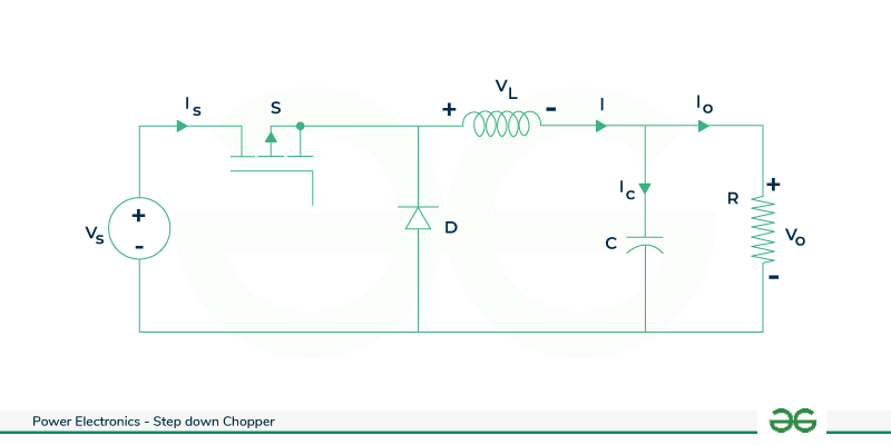
Step-Down Chopper with Low Pass Filter
Case 1 : When the switch S is closed , diode D is reverse biased and supply voltage will charge the inductor .
V0 = Vs - VL
Case 2 : When the switch S is open , inductor L will starts discharging through the diode D and feed the load .
V0 = -VL
VL(on) = Vs – V0
I c(on) = IL – I0
VL(off) = -V0
I c(off) = IL – I0
Since the average voltage across the inductor is zero .
(Vs – V0) Ton + (-V0) (Toff) =0
V0 = Vs .[Ton/(Ton + Toff )]
V0 = Vs . [Ton/T]
V0 = δ .Vs
Where δ= Ton /T
RMS output voltage V 0rms =√ δ. Vs
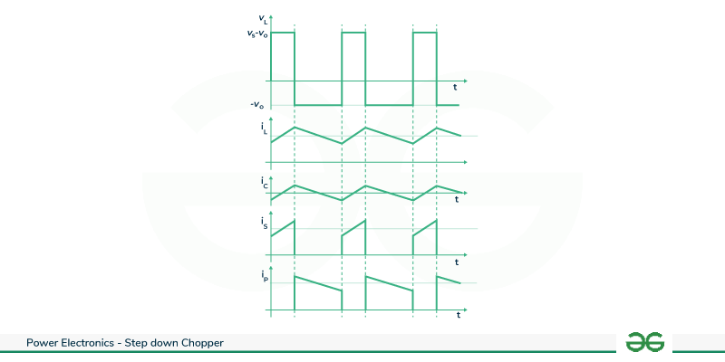
Step Down Chopper With Low Pass Filter
Advantages of Step Down Chopper
- It reduce the input voltage to a lower level making it suitable for applications where low voltage is required.
- They operate at high frequencies , they experiences low switching losses compared to low frequency counterparts. So that efficiency improves and power losses reduced.
- They provide regulated output voltage even when the input voltage fluctuates.
- This maintains stable power supply for sensitive electronic components .
- Compact design.
- As it reduces the voltage , the power dissipated as heat also reduced compared to a linear regulator.
Disadvantages of Step Down Chopper
- It can introduce output voltage ripple due to the switching nature of the device. This ripple can impact sensitive electronic components and may require additional filter circuit.
- Rapid switching of the semiconductor devices in step-down chopper can generate electromagnetic interference .
- Semiconductor devices such as the power switches may experience high voltage stress during operation.
Applications of Step Down Chopper
- These are commonly used in DC motor speed control applications.
- In electric vehicles these are used to control the power supplied to various components , including the traction motor .
- These are used in telecommunication power supplies.
- In UPS systems step-down choppers are used to regulate the voltage and maintain stable output during power interruptions.
- These are used in renewable energy systems such as wind or hydroelectric power plants to convert generated high voltage to a lower and more usable voltage for grid integration.
- These can be utilized in energy harvesting systems to efficiently convert and manage energy from various sources to power low electronic devices .
Conclusion
This is an overview of step-down chopper which consists of step down chopper with different load types , average output voltage derivation , advantages , limitations , applications and problem based on step-down chopper. Step-down chopper is also called as buck converter is a versatile and efficient solution in power electronics . Its ability to reduce voltage while increasing current finds applications in various fields , including power supplies , renewable energy systems and electric vehicles .The step-down chopper’s role minimizing power loss and optimizing energy transfer underscores its significance in enhancing overall energy efficiency .
Solved Example on Step-Down Chopper
Q. A chopper circuit is operating on TRC at a frequency of 2 KHZ on a 460 V supply. If the load voltage is 350 volts , calculate the conduction period of the thyristor in each cycle.
V = 460v, Vdc = 350v , f =2KHz
Chopping period T = (1/f)
T = (1/[2*10-3])
T = 0.5m sec
Output voltage Vdc = (ton/T) * V
Conduction period of thyristor
ton = (T * Vdc)/V
ton = (0.5*10-3 * 350)/ 460
ton =0.38 msec
Conclusion
The future scope of step-down choppers is promising across various industries. As energy efficiency and renewable energy sources gain significance , step-down choppers play a crucial role in power electronics. They are integral components in DC- DC converters, facilitating voltage reduction efficiently. With the growing emphasis on electrical vehicles, renewable energy systems, and portable electronic devices , the demand for compact and high – performance step-down choppers is expected to rise . The development of advanced semiconductor technologies and control algorithms will contribute to increased efficiency and miniaturization. Moreover, the integration of step-down choppers are poised to remain essential in optimizing power distribution , reducing energy consumption , and fostering the transition towards a more sustainable and electrified future.
FAQs on Step Down Chopper
1. What is step-down chopper ?
A step-down chopper is a static device that steps down its input voltage .
2. What is the use of step-down regulator ?
A buck converter also called as buck regulator or DC-DC step-down switching regulator is a type of DC-DC converter that provides an output regulated voltage that is lower than its input voltage .
3. Why is voltage step down?
Increased voltage allows decreased current which dramatically reduces the power losses . So, we decrease voltage at a step down transformer to make it safer and more useable in neighborhood.
Share your thoughts in the comments
Please Login to comment...