Resistors are devices that obstruct the flow of electric current in the circuit. They provide the hindrance to the path of the current which flows in the circuit.
A resistor is a two-terminal electrical component that works by reducing the flow of charge and voltage levels in the circuit. Most of the circuits have one or more resistors to oppose the flow of current and balance the circuit. Most commonly there are two combinations of resistors – Resistors in Series and Parallel.
Resistors in Series
Two or more resistors are in series if the same amount of current flows through all the resistors. In this circuit combination, the voltage across each resistor is different. In series, if any single resistance is damaged then the entire circuit will turn off. The construction process of the series resistor is simpler as compared to parallel.
For example, if we have 3 resistances in series such as R1, R2, R3 then the total equivalent resistance through the circuit is given by
Total Resistance= R1 + R2 + R3

How to identify the resistances are connected in series?
In order to identify the resistance in series we have to observe the circuit carefully. Following are the thing that needs to be kept in mind in order to understand a series resistance:
- Physical Layout: In a series circuit, resistors are linked end-to-end, with current passing through each one sequentially. Tracing the circuit’s path and identifying its components can aid in recognizing the resistors in series.
- Resistance Measurement: We can identify using a multimeter we can measure the resistance of each resistor and then we can calculate their sum an check if it’s equal to the total resistance because in series total resistance is equal to R1 + R2…+ Rn.
- Ohm’s Law: In the case of the overall circuit voltage and total current are known, we can use ohms law V = I*R for determining the total resistance then subtracting known resistor values enables deduction of the remaining series resistors.
- Color Codes or Markings: If resistors have color bands denoting resistance values, a resistor color code chart can decode these values. Compare color bands to the chart to determine resistance. This approach might be unsuitable if resistors lack color bands or visibility.
- Voltage Drop: Measure voltage drops across each resistor using a multimeter. Because if we sum up all voltage drops then it will give the total applied voltage in series circuits, comparing drops helps identify series resistors.
Examples to Identify resistors in series
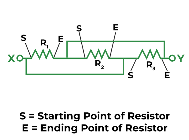
Let’s try to find out series connection in circuits as I have previously explained that series connection means resistors are connected end to end or in the way that end of resistor is connected to starting to the next resistor. While it’s the opposite in the case of parallel circuits, even we can remind from name, series start with s and e meaning starting joined to end and vice versa

Identifying Circuits
Let’s see in the above images where R1 is connected to the end point of R2 and starting point are joined in R1 and R2 so they are in parallel. So first solve these parallel combinations.

Identifying Circuits 2
Now, after solving we can see that the end point of R12 equivalent resistance of R1 and R2 is connected to starting point of the R3 resistor so we can say they are connected in series.
Identifying Circuits 3
Ohm’s law and Kirchoff’s law
Ohms law proposed by Georg Simon Ohm that provides the relationship between the total current flowing in a conductor and the total voltage across it. It states that the current in the circuit is inversely proportional to resistance and directly proportional to the voltage of the circuit.
It is given by
 V = I*R
where,
V = voltage
I = current through the circuit
R = total resistance of the circuit.
Kirchoff’s Law
Two laws are provided by Kirchoff to understand the behavior of electrical circuits
(a) Kirchoff’s Current Law:
It states that the total amount of current entering the junction will be equal to the total amount of current leaving the junction. We can also say that every junction follows the law of conservation of charge.
(b) Kirchoff’s Voltage Law:
It states that for any closed network, voltage around a loop is equal to the sum of voltage drop in the same loop and it is equal to zero.
Example:
Lets consider 3 resistors R1 = 11ohm R2 = 5ohm R3 = 14ohm connected to a 15 Volt battery
i) So, the total equivalent resistance in series will be equal to R1+R2+R3 = 11+5+14 = 30ohm
ii) Calculating the total current using ampere ohm’s law V = I*R,
I = 15/30 = 0.5 ampere
0.5 ampere circuits current will flow through all circuit.
iii) Voltage drops across each resistor are found using Ohm’s Law:
VoltageDropR1 = 5.5V ,VoltageDropR2 = 2.5V ,VoltageDropR3 = 7V
Kirchhoff’s Voltage Law is confirmed by adding the voltage drops, resulting in the battery voltage:
Total Voltage = 5.5V+2.5V+7V=15V
How to solve resistance in series?
i) Circuit Connection
Connect the resistors in series by placing them end to end, one to other. In a series circuit, the current passes through one resistor before flowing through the next. Connect the wires and battery for potential differences.
ii) Calculate Total Resistance
To calculate the total resistance (RT) in the series circuit, add the individual resistance values together:
RT = R1 + R2
RT = 100Ω + 150Ω
RT = 250Ω

iii) Apply Ohm’s Law Using Ohm’s law (V = I * R), you can find the current (I) flowing through the circuit. For this example, let’s assume the applied voltage is 12V.
I = V / RT
I = 12V / 250Ω
I = 0.048A or 48mA
vi) Voltage Drop In a series circuit, the voltage drops across each component add up to the total applied voltage.
Voltage Drop across R1 = I * R1 Voltage Drop across
R1 = 0.048A * 100Ω
= 4.8V
Voltage Drop across R2 = I * R2 Voltage Drop across
R2 = 0.048A * 150Ω
= 7.2V
Practical Examples
Example 1: LED String
We have four LEDs that are connected in series. Each LED has a forward voltage drop of 3V and operates at 20mA. Calculate the appropriate resistor value to limit the current.
Solution:
Total Voltage Drop = 4 LEDs * 3V/LED
= 12V
Remaining Voltage (VR) = Applied Voltage – Total Voltage Drop
= 12V – 12V = 0V
Resistor Value (R) = VR / I
= 0V / 0.020A
= 0Ω
In this case, a resistor with a value of 0Ω is needed to limit the current to 20mA, but since resistors cannot have zero resistance, a practical approach would be to use the nearest standard resistor value, such as 1Ω.
Example 2: Battery Life
Consider a series circuit powered by a 9V battery with three resistors connected in series. The resistors have values of 220Ω, 330Ω, and 470Ω. Calculate the total resistance and the current flowing through the circuit.
Total Resistance (RT) = R1 + R2 + R3
= 220Ω + 330Ω + 470Ω
= 1020Ω
Total Current (I) = V / RT
= 9V / 1020Ω
≈ 0.00882A or 8.82mA
Solving complex circuits
.png)
Steps to solve complex circuits
So, now we will solve the complex circuit with more than one series and parallel combinations.
1. As seen, the resistors 10 and 5 ohm are connected end to end and also the ending point of 10-ohm resistor is joined to starting point of 5-ohm resistor so we add them because for total resistance in series, we need to add all resistors.
.png)
Solving Complex circuit
2. Now three resistors 10Ω, 15Ω, and 20Ω are in parallel best the starting part is connected to starting part of other resistors so we will solve it according to parallel circuits.
Equivalent Resistance = 1/ ((1/10Ω) + (1/15Ω) + (1/20Ω))
= 4.615Ω
.png)
Solving Complex circuits
Now after simplifying the circuit have become very simple we just need to add the resistors in series
Total Resistance of circuit = 5Ω + 4.61Ω
= 9.61Ω
Applications
- Voltage Division: Combining resistors in series forms a voltage divider circuit, useful for generating fractionally scaled output voltages.
- Current Limiting: Series resistors restrict current to prevent component damage, ensuring safe operation.
- LED Current Control: Series resistors prevent LEDs from exceeding safe current levels, extending their lifespan.
- Pull-Up/Pull-Down Resistors: Series-connected resistors set default logic levels in digital circuits, preventing unstable inputs.
- Signal Filtering: Series resistors, paired with capacitors, create filters for shaping signal frequencies.
- Thermistor Networks: Series-connected thermistors and fixed resistors yield temperature-dependent voltage outputs, valuable for temperature sensing.
- Wheatstone Bridge: Four resistors in a diamond pattern form a Wheatstone bridge for measuring unknown resistances.
- Precision Resistor Networks: Series-connected resistors create accurate resistance values, important in precise analog designs.
- Load Distribution: Series resistors aid in distributing current among devices sharing a power supply, ensuring even power delivery.
Advantages of Series Resistance:
- Collective Resistance: Series resistance enables us to attain our desired resistance in the circuit just by adding up all the resistances.
- Consistent Current: Same amount of current flows through all the components in the circuit which simplifies the working and calculation of the circuit.
- Voltage Distribution: Series setups naturally distribute total voltage based on component resistances, making it useful for applications requiring specific voltage divisions.
- Sequential Management: Components in series are linked end-to-end, facilitating sequential control or activation, as seen in LED light strings.
Disadvantages of Series Resistance:
- Increased Total Resistance: Each resistor added in series raises the total resistance, potentially hindering efforts to minimize resistance or increase current.
- Voltage Drop Across Each Resistor: Voltage drop accumulates across each resistor in series, leading to notable voltage loss across the circuit, unsuitable for steady voltage needs.
- Single Failure Point: Failure or disconnection of one resistor disrupts the entire circuit, impacting current flow through the entire series.
- Restricted Flexibility: Modifying resistance in series necessitates adding or changing resistors, providing less flexibility compared to parallel circuits.
- Complexity with Varied Components: Integrating resistors with diverse tolerances or temperature coefficients in a series circuit can yield less predictable and manageable overall behavior.
Frequently Asked Questions of Resistors in Series
Q 1: What will happen if we have multiple resistors in a series but one of them fails?
In a series circuit, if one component fails or opens (has infinite resistance), the entire circuit becomes open, which will spoil the whole circuit and current cannot flow through any component.
Q 2: Can we use series resistance to control the current in a circuit?
Yes, series resistance can be used to limit or control the amount of current to flow in a circuit, as shown in the LED string example above.
Q 3: How to find the total power dissipation in a series circuit?
For power dissipation in a series circuit, use the formula
P = I2 * R,
where,
I is the current flowing through the resistor and
R is the resistance of the component.
Q4. What will be the total resistance if we add more resistance to the circuit?
In series the total resistance is the sum of all the individual resistors the newly added resistance will add up in total resistance and the total resistance will increase.
Q5. How is the current through each resistor related to the total current supplied by the battery in the series circuit?
In series, the amount of current passing through each resistor is equal to the total current supplied.
Share your thoughts in the comments
Please Login to comment...