Microprocessor | 8255 (programmable peripheral interface)
Last Updated :
14 May, 2023
8255 is a popularly used parallel, programmable input-output device. It can be used to transfer data under various condition from simple input-output to interrupt input-output. This is economical, functional, flexible but is a little complex and general purpose i/o device that can be used with almost any microprocessor.
8255 pin diagram –
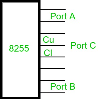
It has 24 pins that can be grouped in two 8-bit parallel ports: A and B called Port A(PA) and Port B(PB) with the remaining eight known as Port C(PC). Port C can be further divided into groups of 4-bits ports named Cupper(Cu) and Clower(Cl). There are 40 pins and operates in +5 regulated power supply.
Modes of 8255 – It works in two modes:
- Bit set reset (BSR) mode
- Input/output (I/O) mode
To know in which mode the interface is working we need to know the value of Control word. Control word is a part of control register in 8255 which specify an I/O function for each port. This is format of control word 8255.
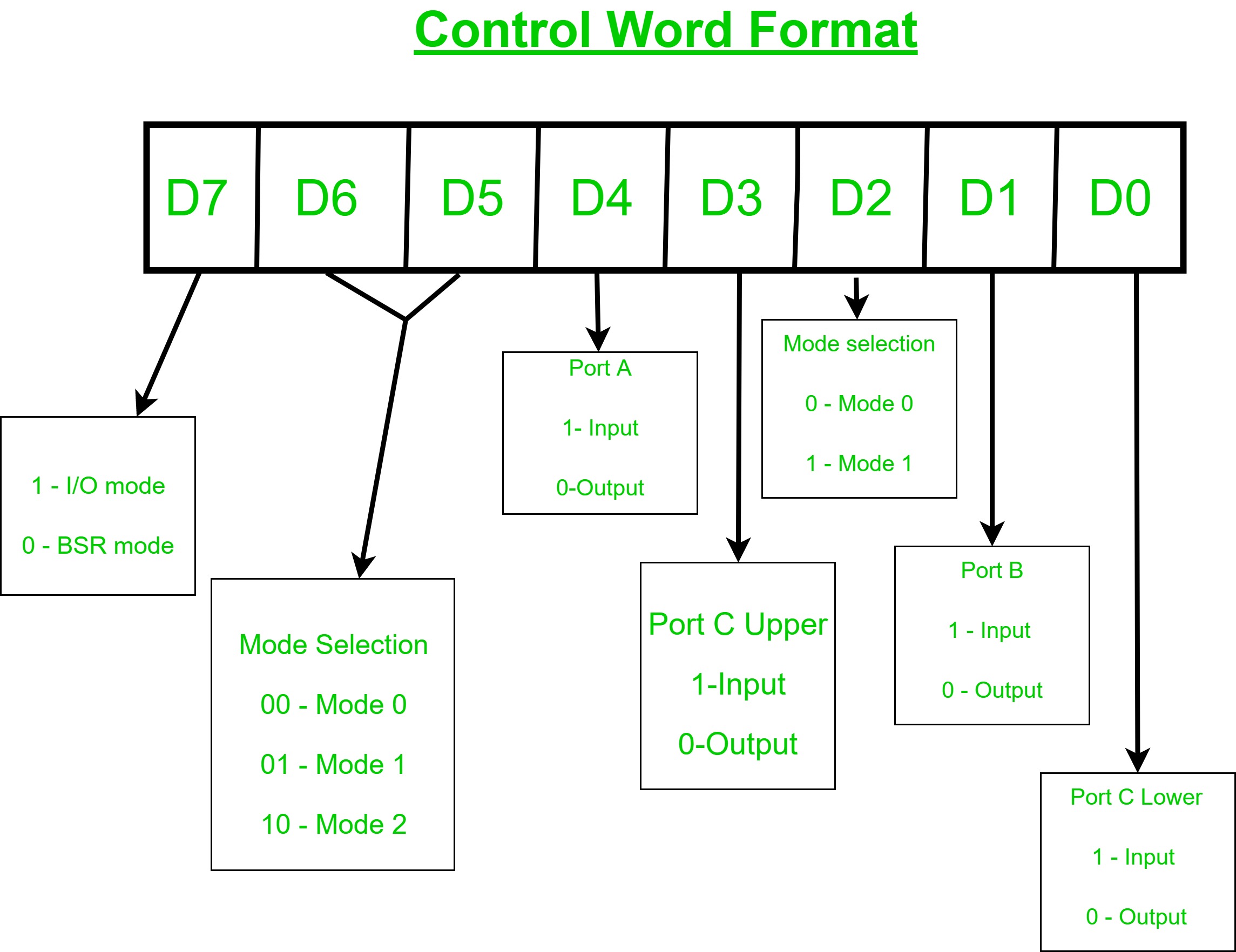
If the most significant bit of control word or D7 is 1 then 8255 works in I/O mode else, if it’s value is 0 it works in BSR mode.
- BSR Mode – When MSB of the control register is zero(0), 8255 works in Bit Set-Reset mode.in this only PC bit are used for set and reset.
- I/O Mode – When MSB of the control register is one(1), 8255 works in Input-Output mode.it is further divided into three categories.
- Mode 0 – In this mode all three ports (PA, PB, PC) can work as simple input function or output function also in this mode there is no interrupt handling capabilities.
- Mode 1 – In this either port A or port B can work and port C bits are used as Handshake signal before actual data transmission plus it has interrupt handling capabilities.
- Mode 2 – In this only port A works and port B can work either in Mode 0 or Mode 1 and the 6 bits of port C are used as Handshake signal plus it also has to interrupt handling capability.
To communicate with peripherals through 8255 three steps are necessary:
- Determine the addresses of Port A, B, C and Control register according to Chip Select Logic and the Address lines A0 and A1.
- Write a control word in control register.
- Write I/O instructions to communicate with peripherals through port A, B, C.
The common applications of 8255 are:
- Traffic light control
- Generating square wave
- Interfacing with DC motors and stepper motors
Advantages:
Flexibility: A microprocessor with an 8255 PPI allows for flexible input/output (I/O) operations. The PPI can be programmed to operate in a variety of modes, and the microprocessor can handle the data transfer between the PPI and other devices.
Improved system performance: The use of a microprocessor with an 8255 PPI can improve system performance by offloading I/O operations from the CPU. This allows the CPU to focus on other tasks while the PPI handles the data transfer.
Easy to interface with other devices: The 8255 PPI can be easily programmed and interfaced with other devices, which makes it easy to use in a variety of applications.
Low cost: The 8255 PPI is a relatively low-cost component, which makes it an affordable option for many different applications.
Disadvantages:
Complexity: Using a microprocessor with an 8255 PPI can add complexity to a system, particularly for novice programmers. The PPI requires programming, and the microprocessor must be programmed to handle the data transfer between the PPI and other devices.
Limited functionality: While the 8255 PPI is versatile, it has limited functionality compared to newer I/O interface components. It is not capable of high-speed data transfer and has limited memory capacity.
Limited number of ports: The 8255 PPI provides only three 8-bit ports, which may not be sufficient for some applications that require more I/O ports.
Obsolete technology: While the 8255 PPI is still used in some applications, it is considered an older technology and is being replaced by newer, more advanced I/O interface components.
Share your thoughts in the comments
Please Login to comment...