The inductor is a passive element that is used in electronic circuits to store energy in the form of magnetic fields. It is usually a thin wire coiled up of several turns around a ferromagnetic material. Inductors are used in transformers, oscillators, filters, etc. The amount of energy that can be stored by the inductor in the form of the magnetic field is called inductance measured in Henry named after the famous scientist Joseph Henry.
Inductor works on the principle of one of Maxwell’s four equations which states that a changing electric field produces a changing magnetic field and vice versa. Unlike a capacitor, an inductor cannot sustain the stored energy as soon as the external power supply is disconnected because the magnetic field decreases steadily as it is responsible for current flow in that circuit in the absence of the power supply.
What is Inductor I-V Equations?
The I-V (current-voltage) equations for an inductor describe how the current flowing through an inductor changes in response to changes in voltage applied across it. We have derived both differential and integral forms of I-V equations for an inductor. They are as follows:
Differential Form
[Tex]V = \frac{d\Phi}{dt}[/Tex]forms
Integral Form
[Tex]I = \frac{1}{L}\int Vdt[/Tex]
From the differential form of I-V equation, we can find the value of voltage across the inductor if we already know the value of inductance and rate of change of current flowing through the inductor. Whereas using integral form, we can find the current flowing through the inductor if we know the inductance and voltage across the inductor.
Relation Between Current and Voltage
Below steps can be followed to derive the relation between current flowing through an inductor and voltage across it. Magnetic flux present across the inductor is equal to it’s inductance times current flowing through it.
Mathematically, it can be written as:
[Tex]\Phi = LI[/Tex]
Also induced voltage across the inductor is equal to the rate of change of magnetic flux per unit time.
[Tex]V = \frac{d\Phi}{dt}[/Tex]
Substituting the value of Φ in above equation we get,
[Tex]V = \frac{dLI}{dt}\\
\hspace{1mm}\\
\therefore V = L\frac{dI}{dt}[/Tex]
The above equation describes the relation between voltage and current respectively. The above equation can be easily rearranged to find current if we know voltage and inductance beforehand.
[Tex]\frac{V}{L} = \frac{dI}{dt}\\
\hspace{1mm}\\[/Tex]
Integrating both sides with respect to time,
[Tex]I = \int \frac{V}{L}dt\\
\hspace{1mm}\\
\therefore I = \frac{1}{L}\int Vdt[/Tex]\
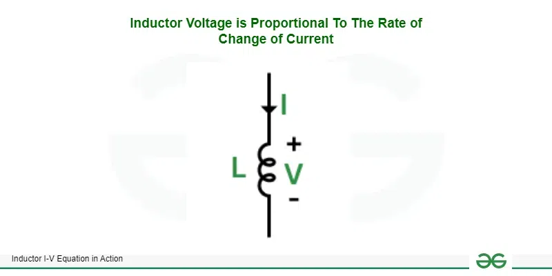
Inductor Voltage is Proportional To The Rate of Change of Current
From the differential form of I-V equation, we can see that voltage across the inductor is directly proportional to rate of change of current flowing through the inductor (time derivative of current) where inductance L is the proportionality constant. We know that when current flows through a conductor, it generates a magnetic field around the conductor.
A time varying current flow generates a time varying magnetic field whose polarity changes based on the direction of the current flow. This time varying magnetic field generates voltage across the inductor due to faraday’s law. The generated voltage totally depends on the inductance of the inductor. However there is a phase difference of 90° and current lags voltage in an inductor.
Voltage across inductor
Let I = sin(ωt)
[Tex]V = L\frac{dsin\omega t}{dt}\\
\hspace{1mm}\\
\therefore V = Lcos(\omega t)[/Tex]
Hence voltage leads current by 90° and is scaled by factor of inductance L
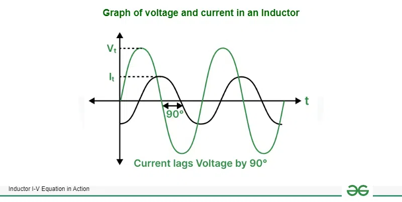
Graph of voltage and current in an inductor
Inductor and Current Source
When an inductor having inductance L = 1 mH is connected to a constant current source I = 1 mA. To find the voltage drop across the inductor we can use one of the above derived equations which results in,
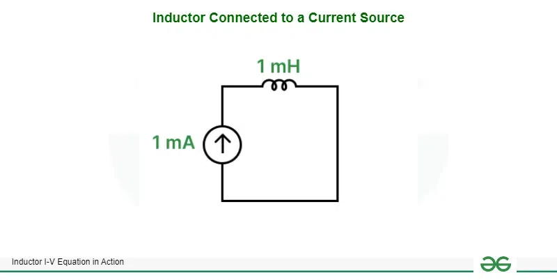
Inductor connected to a current source
[Tex]V = L\frac{dI}{dt}\\
\hspace{1mm}\\
V = 10^{-3}\frac{d10^{-3}}{dt}\\
\hspace{1mm}\\
V = 10^{-3}\times 0\\
\hspace{1mm}\\
\therefore V = 0 \hspace{1mm} volts[/Tex]
The above proof is valid for inductor having inductance and irrespective of the current supplied by the constant current source because the derivative of a constant is always zero and anything multiplied by zero becomes zero.
Inductor and Voltage source
Given Below is the circuit of Inductor and Voltage Source
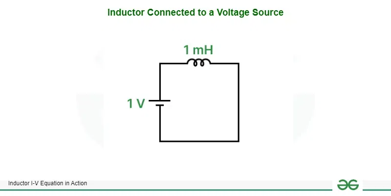
Inductor connected to voltage source
Instead of a current source let us consider a voltage source V = 1 V connected to an inductor having inductance L = 1 mH. We can find the current flowing through it with the help of our derived equation of relation between current and voltage in an inductor.
[Tex]I = \frac{1}{L}\int_{0}^{T}Vdt\\
\hspace{1mm}\\
I = \frac{1}{10^{-3}}\int_{0}^{T}1dt\\
\hspace{1mm}\\
I = 10^3[t]_{0}^{T}\\
\hspace{1mm}\\
I = 10^3[T-0]\\
\hspace{1mm}\\
I = 10^3T\\
\therefore I = 1000 \hspace{1mm} A/sec[/Tex]
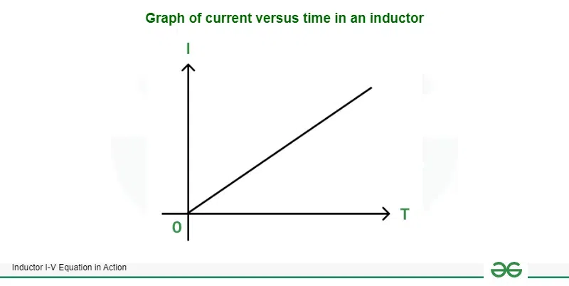
Graph of current versus time in an inductor
We can see that the current increases linearly with a rate of 1 kA/sec if we connect a constant voltage source. Practically, the voltage source cannot supply such enormous amounts of current and even if it was capable, the circuit would get damaged due to wires and inductor itself melting down due to high current flow. Hence we must connect a switch along with the inductor to provide short pulses of voltage instead of providing steady voltage throughout the entire time. This will reduce the peak current which flows through the circuit.
Inductor and Switch
Given below is Inductor with Voltage Pulse
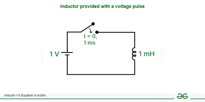
Inductor provided with a voltage pulse
Graph of Voltage Pulse is given below
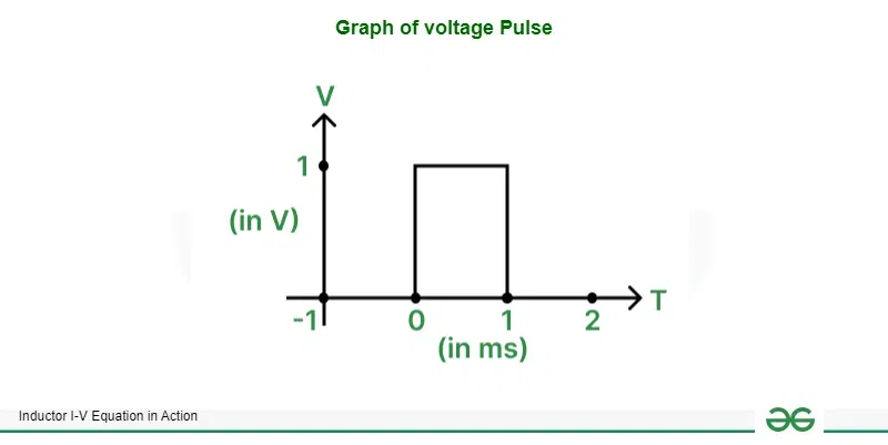
Graph of voltage Pulse
To solve the issue of linearly increasing current in the circuit due to constant voltage source we have introduced a switch which is closed for a short period of time to provide a voltage pulse. A voltage pulse having amplitude 1V and width of 1 ms is provided to an inductor having inductance 1 mH. There are three cases for which we have to find the current flowing in the circuit, which are before closing the switch, after closing switch and during opening the switch.
Before switch is closed
Before the switch is closed, the circuit is not completed and no current flows through the inductor. Also there is no magnetic field existing across the inductor. Hence I0 = 0.
[Tex]I = \frac{1}{L}\int_{-E}^{0}Vdt+I_{0}\\
\hspace{1mm}\\
I = \frac{1}{10^{-3}}\int_{-E}^{0}0dt + 0\\
\hspace{1mm}\\
I = 10^{3}[0]_{-E}^{0}\\
\hspace{1mm}\\
I = 10^{3}[(0\times0)-(0\times-E)]\\
\hspace{1mm}\\[/Tex]
∴ I = 0 A for any value of E
After switch is closed
At t = 0, the switch is closed for 1 ms making a closed circuit for this particular duration. The current in the circuit steadilty increases according the formula,
[Tex]I = \frac{1}{L}\int_{0}^{T}Vdt+I_{0}\\
\hspace{1mm}\\
I = \frac{1}{10^{-3}}\int_{0}^{10^{-3}}1dt+0\\
\hspace{1mm}\\
I = 10^3[t]_{0}^{10^{-3}}\\
\hspace{1mm}\\
I = 10^3[10^{-3}-0]\\[/Tex]
∴ I = 1 A
After 1 ms the switch is opened stopping the current flow to the inductor.
During switch is opened
A problem arises during the opening of the switch. Theoretically if we try to find voltage across the inductor during this period, it comes to infinity since the current abruptly changes from 1 A to 0 A due to opening of the circuit. However practically the current takes some time let us consider it as 1 μs. To find the practical voltage across the inductor,
[Tex]V = L\frac{dI}{dt}\\
\hspace{1mm}\\
V = 10^{-3}[\frac{0-1}{10^{-6}}]\\
\hspace{1mm}\\
V = -\frac{1}{10^{-3}}\\
\hspace{1mm}\\
V = -10^3[/Tex]
∴ V = -1 kV
Such high voltages cause arcs and electric current starts to travel through air. This process only stops after the inductor does not have any current stored in the form of magnetic field. These arcs are dangerous and can be avoided by connecting a diode which acts as a safe path to discharge the inductor. A diode is a semiconductor device which allows the current to flow in only one direction. In the below circuit diagram, the diode conducts while the switch is being opened and discharges the inductor. When the switch is closed, no current flows through the diode.
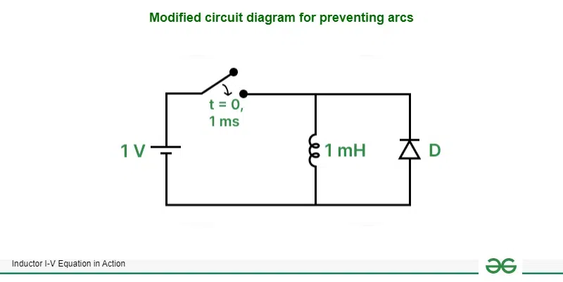
Modified circuit diagram for preventing arcs
Solved Examples
Find peak current flowing through an inductor having an inductance of 100 mH connected with a voltage pulse generator having amplitude of 5 V and pulse width of 0.1 ms.
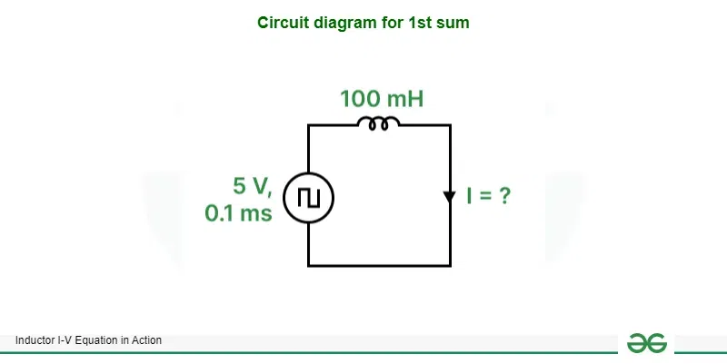
Circuit diagram for 1st sum
[Tex]I = \frac{1}{L}\int_{0}^{T}Vdt\\
\hspace{1mm}\\
I = \frac{1}{100\times10^{-3}}\int_{0}^{0.1\times{10^{-3}}}5dt\\
\hspace{1mm}\\
I = \frac{1}{10^{-1}}\int_{0}^{10^{-4}}5dt\\
\hspace{1mm}\\
I = 10[5t]_{0}^{10^{-4}}\\
\hspace{1mm}\\
I = 10[(5\times{10^{-4}})-(5\times0)]\\
\hspace{1mm}\\
I = 5\times{10^{-3}}\\[/Tex]
∴ I = 5 mA
Find the inductance of an inductor connected with constant voltage source of 12 V switched at t = 0 for 1 ms. The peak current flowing through the circuit is 100 mA.
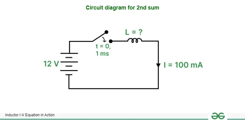
Circuit diagram for 2nd sum
[Tex]I = \frac{1}{L}\int_{0}^{T}Vdt\\
\hspace{1mm}\\
L = \frac{1}{100\times10^{-3}}\int_{0}^{10^{-3}}12dt\\
\hspace{1mm}\\
L = \frac{1}{10^{-1}}\int_{0}^{10^{-3}}12dt\\
\hspace{1mm}\\
L = 10[12t]_{0}^{10^{-3}}\\
\hspace{1mm}\\
L = 10[(12\times{10^{-3}})-(12\times0)]\\
\hspace{1mm}\\
L = 12\times{10^{-2}}\\[/Tex]
∴ L = 120 mH
Find the voltage across the load resistor of 10 kΩ connected across an inductor having inductance of 15 mH. The entire circuit is powered by a voltage pulse generator which generates 9 V pulses having a pulse width of 2 μs.
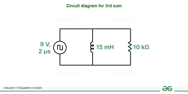
Circuit diagram for 3rd sum
[Tex]I = \frac{1}{L}\int_{0}^{T}Vdt\\
\hspace{1mm}\\
I = \frac{1}{15\times10^{-3}}\int_{0}^{2\times{10^{-6}}}9dt\\
\hspace{1mm}\\
I = \frac{10^3}{15}\int_{0}^{2\times{10^{-6}}}9dt\\
\hspace{1mm}\\
I = 66.67[9t]_{0}^{2\times{10^{-6}}}\\
\hspace{1mm}\\
I = 66.67[(9\times2\times{10^{-6}})-(9\times0)]\\
\hspace{1mm}\\
I = 1.2\times{10^{-3}}\\
\hspace{1mm}\\
V = IR\\
\hspace{1mm}\\
V = 1.2\times10^{-3}\times10000\\[/Tex]
∴ V = 12 V
Conclusion
We can conclude that this article helped viewers to understand the basics of inductor, derived the equations which describes the operating principle of inductor and solved some numerical based on those formulae.
Inductor I-V Equation in Action – FAQs
What is the difference between inductance and inductive reactance?
Inductance is the property of a conductor to oppose the incoming current for a short duration. When current flows through an inductor, a magnetic field is formed whose direction can be determined by right hand thumb rule. This steadily rising magnetic field generates a voltage which oppose the incoming current. Hence this is also called as Back EMF. Inductive reactance is this opposing voltage measured in ohms since it restricts the flow of current through the inductor. It is directly proportional to frequency of applied signal.
What is mutual inductance?
When alternating current flows through an inductor it generates a time varying magnetic field around itself. When another inductor is placed near the first inductor, the magnetic field lines cuts it and generates a voltage across the second inductor. This property is called as mutual inductance and it is used in transformers to either step-up or step-down the voltage.
Why loops of wire are required to create an inductor?
When current flows through a straight wire, it creates magnetic field around the wire. When this current supply is stopped, the magnetic field decreases rapidly. However this decreasing magnetic field does not pass through any wire and does not create a back EMF required for an inductor to work. Hence by creating loops of wires the magnetic flux density increases and when current stops, the rapidly decreasing magnetic field cuts through the spiral wires generating back EMF.
Share your thoughts in the comments
Please Login to comment...