How to Design ER Diagrams for Project Management Software
Last Updated :
27 Feb, 2024
Designing an Entity-Relationship (ER) diagram for project management software involves creating a database schema that can efficiently store and manage project-related information. This includes details about projects, tasks, users, and dependencies between them.
In this article, we’ll explore the process of designing an ER diagram for project management software, focusing on key entities, attributes, relationships, and best practices for database design.
ER Diagrams Design for Project Management Software
Designing an Entity–Relationship (ER) diagram for project management software is important for organizing and structuring the database that will efficiently handle projects, tasks, users, and their relationships.
An ER diagram visually represents the data model, including entities, attributes, and relationships helping developers and stakeholders understand the system data requirements and design.
Project Management Software Features
- Project Management: The software allows users to create and manage projects. Each project can have a name, description, start date, end date, and status (For example: ongoing, completed, or delayed). This feature enables users to track the progress of their projects and ensure they are completed on time.
- Task Management: Users can create tasks within each project, assign them to team members and track their progress. Tasks have attributes such as name, description, start date, end date and status. This feature helps in organizing the work required for each project and ensures that tasks are completed on schedule.
- User Management: The software allows administrators to manage user accounts. Users can have different roles (For example: project manager, or team member) with varying levels of access and permissions. User profiles include information such as name, email address and role. This feature ensures that only authorized users can access sensitive project information.
- Reporting: The software provides reporting features that allow users to generate various reports related to project progress, task completion and resource allocation. These reports help in evaluating the performance of the project and making informed decisions for future projects.
Overall, these features make the project management software a valuable tool for organizing and managing projects effectively, ensuring that they are completed on time and within budget.
Entities and Attributes of the Project Management Software
Project Management Software (PMS) plays a crucial role in efficiently managing projects, tasks, resources, and timelines. An Entity-Relationship Diagram (ERD) is a visual representation that helps us understand the data structure and relationships within a project management system. In this article, we’ll delve into the process of designing an ERD specifically for project management software.
1. Company: Represents the organization or client undertaking the project.
- CompanyID: Unique identifier for the company
- Name: It is the name of the Company.
- Industry: Industry in which company operates in.
- Location: It is a Address or headquarters location.
- Website: It is a Company website URL.
- Contact Information: It is an Email address, phone number.
2. Project: Represents a specific task or venture within the company.
- ProjectID: Unique identifier for the project.
- Name: Project title.
- Description: Brief overview of the project goals and objectives.
- Start Date: Date the project officially begins.
- End Date: Projected completion date.
- Budget: Total allocated budget for the project.
- Status: Current project status (e.g., Active, On Hold, Completed).
- Priority: Project priority level (e.g., High, Medium, Low).
- CategoryID: Foreign key referencing the associated Project Category.
3. Project Member: Individuals involved in different aspects of the project, with varying roles and responsibilities.
- MemberID: Unique identifier for the project member.
- Name: Member’s full name.
- Email: Member’s contact email address.
- Role: Specific role within the project (e.g., Developer, Designer, Project Manager).
- Skills: List of relevant skills and expertise.
- Availability: Percentage of time dedicated to the project.
4. Project Manager: Leads and oversees the overall project execution, ensuring completion within scope, budget, and timeline.
- ManagerID: Unique identifier for the project manager.
- MemberID: Foreign key referencing the associated project member (assuming Project Manager is also a member).
- AdditionalResponsibilities: Specific responsibilities beyond general project management.
5. Project Update: Tracks progress, issues or other relevant information shared on the project.
- UID: Unique identifier for the update.
- ProjectID: Foreign key referencing the associated project.
- MemberID: Foreign key referencing the member who posted the update.
- Timestamp: Date and time the update was posted.
- Content: The actual update information (e.g., progress report, issue description, solution proposal).
- Type: Categorization of the update (e.g., General Progress, Issue, Risk, Decision).
- Status: Current status of the task (e.g., To Do, In Progress, Completed).
Relationships Between These Entities
1. Company – Project (One-to-Many):
- One company can have many projects.
- This can be implemented with a foreign key in the Project table referencing the CompanyID in the Company table.
2. Project – Project Member (One-to-Many):
- One project can have many members.
- This can be implemented with a foreign key in the Project Member table referencing the ProjectID in the Project table.
3. Project – Project Update (One-to-Many):
- One project can have many updates.
- This can be implemented with a foreign key in the Project Update table referencing the ProjectID in the Project table.
4. Project – Skill (Many-to-Many):
- A project can require many skills, and a skill can be used in many projects.
- This can be implemented with an additional table ProjectSkill linking projects and skills with foreign keys to both tables.
5. Project Member – Project Manager (Many-to-Many):
- A project member can be a project manager for multiple projects and a project manager can manage multiple projects.
- This can be implemented by adding a ProjectManagerID (foreign key to Project Manager) to the Project Member table with the possibility of being NULL for non-manager members.
6. Project Member – Project Manager (One-to-One):
- A project member can be a project manager for one project at a time (assuming you have unique project managers).
- This can be implemented by making the ProjectManagerID in the Project Member table a foreign key to the ManagerID in the Project Manager table, and ensuring it’s either unique or allows NULL values for non-manager members.
Representation of ER Diagram
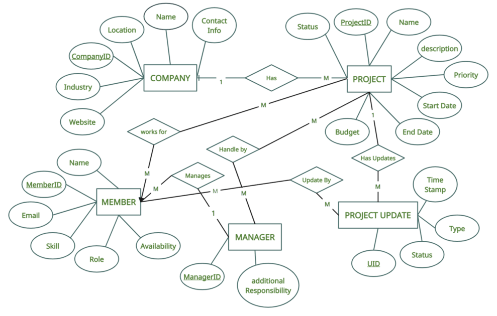
ER Diagram for Project Management Software
Tips and Tricks to Improve ER Diagram
- Normalization: Decomposing complex entities into smaller, atomic ones to minimize redundancy and improve data integrity.
- Data Types: Selecting appropriate data types (For Example: integers, dates, strings) for attributes based on their nature.
- Constraints: Enforcing rules (For Example: primary keys, unique constraints) to ensure data consistency and validity.
- Refine and Optimize: Eliminate redundancy by merging entities with similar attributes or relationships.
- Use normalization techniques to minimize data duplication and improve data integrity.
- Clarity and simplicity: Use clear symbols, concise labels, and avoid unnecessary complexity.
- Consistency: Maintain consistent notation and style throughout the diagram.
- Accuracy: Ensure the diagram accurately reflects the real-world data model.
- Completeness: Include all relevant entities, attributes and relationships.
- Readability: Make it easy to understand for technical and non-technical audiences.
Conclusion
Overall, Designing an ER diagram for project management software requires careful consideration of the entities, attributes, and relationships involved. By following best practices and considering the specific requirements of the project, developers can create a database schema that efficiently manages project-related data. Now you can easily Create an ER Diagram for Project Management Software
Share your thoughts in the comments
Please Login to comment...