Cycloconverters are power electronic devices designed to convert electric power directly from one frequency to another, typically without the need for an intermediate DC link. Additionally, they are employed in specialized systems where precise control of output frequency and low harmonic distortion are crucial. However, challenges include complexity in control strategies and the presence of harmonics in the output waveform, requiring careful design and control for optimal performance. A cycloconverter is thus a one-stage frequency changer. The fundamental principle of a cycloconverter involves breaking down the input AC power into smaller segments and reassembling them to form the desired output frequency.
In this Article, We will be going through Cycloconverter in power electronics, We will go through what is a Cycloconverter, its Type with its Construction, and its Characteristics, At last, we will conclude our Article with Some Solved Examples and FAQs.
What is a Cycloconverter?
Unlike traditional converters that utilize rectifiers and inverters, cycloconverters directly process AC signals. They are commonly employed in applications requiring variable speed control of AC motors and are particularly useful in high-power and low-frequency scenarios. Due to their direct frequency conversion capability, cycloconverters are capable of applications such as industrial drives, large-scale power systems, and specialized machinery. They offer advantages such as simplicity, reduced harmonics, and the ability to handle variable frequencies without an intermediate DC stage. They find applications in areas like motor drives, renewable energy systems, and high-frequency induction heating.
There are two main types of cycloconverters: single-phase and three phase. Single-phase cycloconverters are simpler and suitable for lower power applications, while three-phase cycloconverters are used in high-power industrial applications. One of the key applications of cycloconverters is in adjustable speed drive systems. In industrial settings, precise control of motor speed is often critical for optimizing processes such as metal rolling, paper manufacturing, and mining operations. Cycloconverters enable variable speed and torque control, leading to enhanced operational efficiency and energy savings.
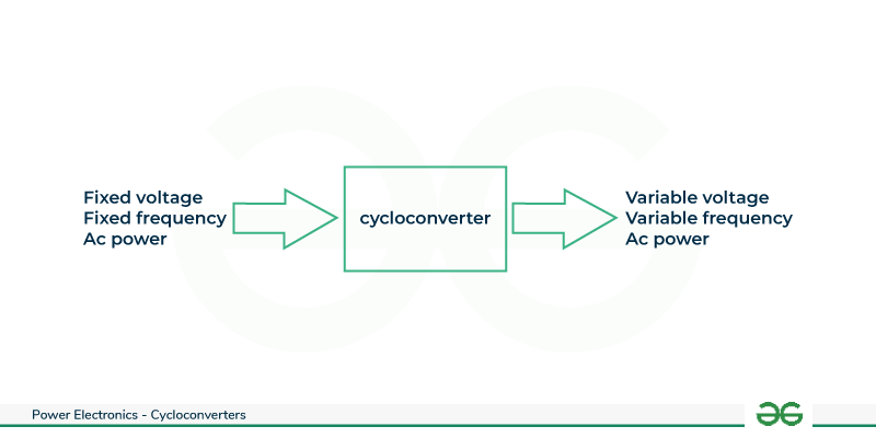
Block-Diagram-of-Cycloconverter
Types of Cycloconverters
Based on the Output of the Frequency and the total numbers of phase in the input Ac power the Cycloconverters can be classified as
- Step Down Cycloconverters
- Step Up Cycloconverters
Step Down Cycloconverters
In step-down cycloconverters , the output frequency f0 is lower than the supply frequency fs . i.e. f 0 < fs . These converters commonly used to control the speed of AC motors. Unlike traditional converters , step down cycloconverters operate without intermediate DC stages , directly transforming the input power . They consist of thyristor based switching circuits that facilitate frequency reduction. This allows for efficient and reliable speed control in applications , making step-down cycloconverters valuable in industries where precise motor speed adjustments are crucial such as in manufacturing and transportation systems.
Step Up Cycloconverters
In step-up cycloconverters , the output frequency f0 is more than the supply frequency fs .i.e.. f0 > fs . It operates by chopping and recombining the input waveform , enabling an increase in frequency. Unlike traditional cycloconverters , step-up cycloconverters provide an output voltage with a higher frequency than the input , making them useful in applications requiring elevated power supply frequencies. These converters find applications in variable speed drives , renewable energy systems etc.
Construction and Components of Cycloconverter
Cycloconverters consists of power electronic components such as thyristors which are arranged in specific configurations to achieve frequency conversion. The basic construction involves connecting these semiconductor devices in either single phase or three phase configurations , depending on the application. Control circuitry governs the firing angles of the thyristors , determining the timing of power switching. The input AC waveform is then segmented and rearranged to produce the desired output frequency. adequate heat sinks and cooling systems are essential to manage heat dissipation. Overall, the construction of cycloconverters requires careful arrangement and control of semiconductor devices to achieve efficient and precise AC frequency conversion.
- Converter Bridge : The converter bridge is the core component responsible for the frequency conversion. It typically consists of silicon controlled rectifiers or thyristors arranged in a specific configuration. The firing of these devices is controlled to shape and manipulate the output waveform.
- Firing circuit : The firing circuit controls the firing angle of the thyristors in the converter bridge. It determines when the thyristors are triggered to conduct , allowing the cycloconverter to control the output frequency.
- Transformer : Transformers are used to step down or step up the voltage as required for the application. They provide isolation between the input and output sides of the cycloconverters.
- Filtering components: Filters are often used to reduce harmonics and smooth the output waveform . They help to improve the quality of output power and reduce the interference with other electrical systems .
- Snubber circuits: These are used to suppress voltage spikes and reduce stress on the thyristors. They help protect the thyristors from voltage transients during switching.
Characteristics and Need of Cycloconverter
- A cycloconverter is a power electronic device that converts alternating current at one frequency to other frequency. One of its key characteristics is its ability to provide variable output frequency and voltage , making it suitable for diverse applications like motor speed control and induction heating.
- Cycloconverters are known for their robustness and reliability due to their minimal use of semiconductor devices , reducing the risk of component failure.
- They exhibit low harmonic distortion , enhancing power quality and reducing electromagnetic interference .Despite their efficiency , cycloconverters may have lower power factor compared to other converters , requiring power factor correction in certain applications. Additionally , their complex control systems demand advanced electronic circuits and sophisticated control algorithms.
Cycloconverters serve a crucial role in various industrial applications due to their unique capabilities .One significant need for cycloconverters lies in adjustable speed drive systems , where precise control of motor speed is essential for processes such as steel rolling mills , paper manufacturing , and mining operations. The ability of cycloconverters to convert power from one frequency to another makes them invaluable in systems requiring variable speed and torque control, enhancing operational efficiency and energy savings. In applications like induction heating , where precise temperature control is vital, cycloconverters provide a reliable means to adjust power output and frequency, optimizing the heating process. The need for cycloconverters arises from their versatility in adapting power supply characteristics to meet specific requirements of diverse industrial processes , contributing to improved efficiency and overall system flexibility.
Based on the working principle they are classified as :
- Single-Phase to Single-Phase Cycloconverter
- Three-Phase to Single-Phase Cycloconverter
- Three-Phase to Three-Phase Cycloconverter
Types of Step Up Cycloconverters
The Two Types of SCyclo Conveters are Given Below
- Mid Point Step Up Cycloconverter
- Bridge Type Step Up Cycloconverter
Mid Point Step Up Cycloconverter
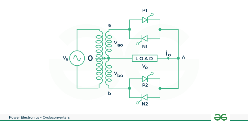
It consists of a single -phase transformer with mid tap on the secondary winding and four thyristors . Two of these thyristors P1, P2 are for positive group and the other two N1, N2 are for the negative group. Load is connected between secondary winding mid point ‘o’ and terminal A as shown . During the positive half cycle of supply voltage of terminal a is positive with respect to terminal b. Therefore , in this positive half cycle both SCRs P1 and N2 are forward biased from ωt = 0 to π . When SCR P1 is turned on at ωt = 0 then the load voltage is positive with terminal A positive and terminal o negative. The load voltage now follows the positive envelope of the supply voltage . At instant ωt1 , P1 is force commutated and forward biased thyristor N2 is turned on so that load voltage is negative with terminal o positive and terminal A negative . The load , or output voltage now traces the negative envelope of the supply voltage.
.png)
Cycloconverter Circuit
At instant ωt2 , N2 is force commutated and forward biased thyristor P1 is turned on so that load voltage is positive and follows the positive envelope of supply voltage. After ωt = π terminal b is positive with respect to terminal a ; both SCRs P2 and N1 are therefore forward biased from ωt = π to 2 π . At ωt = π , N1 is force commutated and forward biased SCR P2 is turned on. In this manner , SCRs P1 and N2 for first half cycle ; P2 and N1 for second half cycle and so on are switched alternatively between positive and negative envelopes at a high frequency . As a result output frequency f0 , is higher than the supply frequency fs as shown with f0 = 6fs .
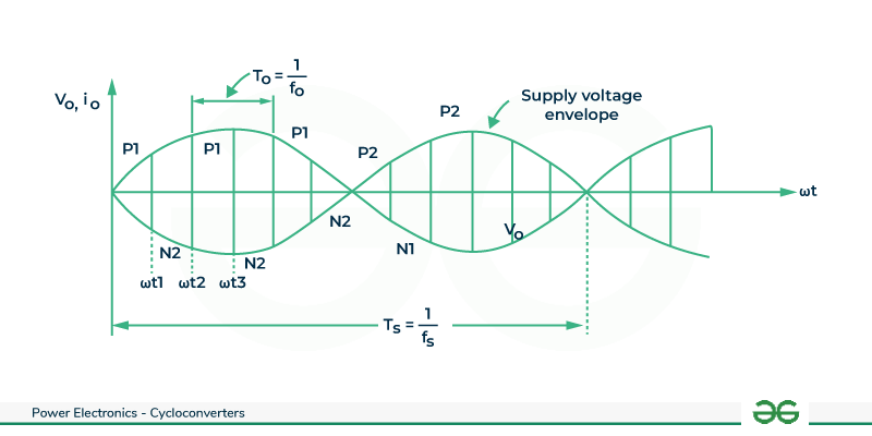
Mid Point Step Up Cycloconverter Waveform
Bridge Type Step Up Cycloconverter
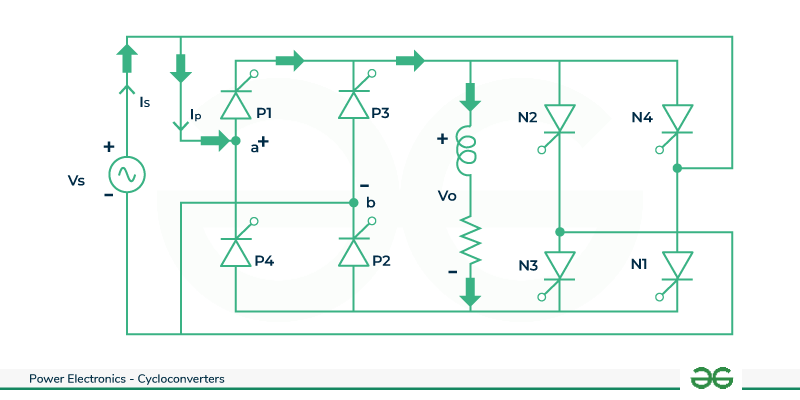
It consists of a total of eight thyristors , P1 to P4 i.e. four for positive group and the remaining four for the negative group N1 to N4. When a is positive with respect to x i.e. during the positive half cycle of supply voltage pairs P1 , P2 and N1, N2 are forward biased from ωt = 0 to π . When forward biased thyristors P1 , P2 are turned on together at ωt = 0 , the load voltage is positive with respect to x , so that load voltage is positive with terminal A positive with respect to o . Load voltage now traverses the positive envelope of supply voltage .
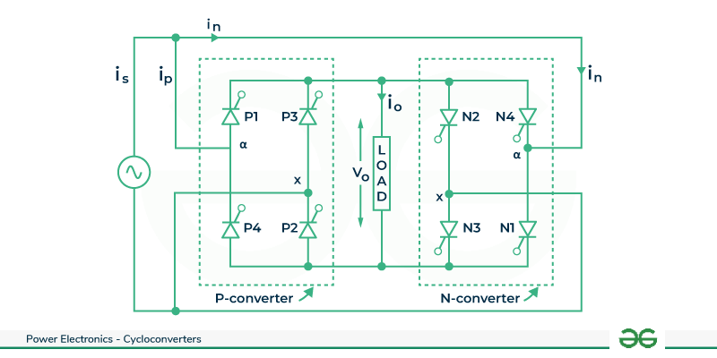
Bridge Type Step Up Cycloconverter Circuit
At ωt1 , SCRs P1 and P2 are force commutated and forward biased pair N1 , N2 are turned on. With this , load voltage is negative with terminal o positive with respect to A. Load voltage now follows the negative envelope of source voltage. At ωt2 , N1 and N2 are force commutated and P1 and P2 are turned on. The load voltage is now positive and follows the positive envelope of source voltage. After ωt = π , thyristor pairs P3 , P4 and N3 , N4 are forward biased , these can therefore be turned on and force commutated from ωt = π to 2 π . In this manner, a high frequency turning on and force commutation of pairs P1 P2 , N1 N2 and pairs P3 P4 , N3 N4 gives a carrier frequency modulated output voltage across load terminals .
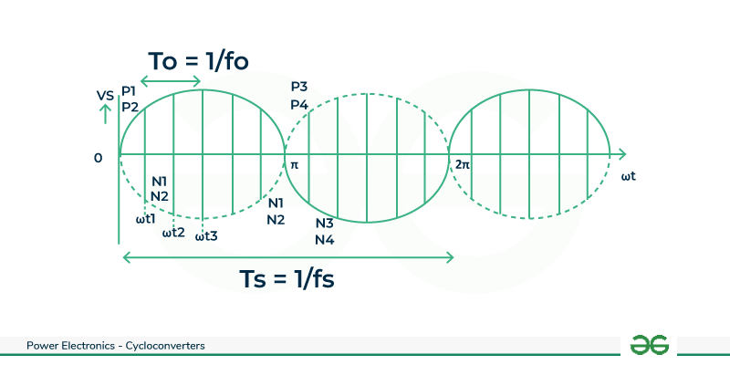
Bridge Type Step Up Cycloconverter Waveform
Types of Step Down Cycloconverter
Two types of Step Down Cycloconveters are
- Mid Point Step Down Cycloconverter
- Bridge-Type Step Down Cycloconverter
Mid Point Step Down Cycloconverter
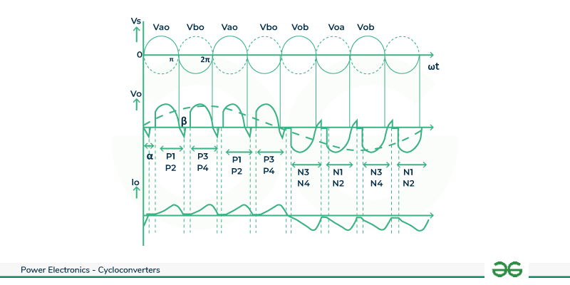
A step down cycloconverter does not require forced commutation . It requires phase controlled converters connected as shown . During positive half cycle terminal A is positive with respect to o , P1 is triggered at ωt = π , positive output voltage appears across load and load current starts building up. At ωt = π , supply and load voltages are zero. After ωt = π, P1 is reverse biased. As load current is continues , P1 is not turned off at ωt = π . When P2 is triggered in sequence at ωt = π + α , reverse voltage appears across P1 , it is therefore turned off by natural commutation. When P1 is commutated , load current has built up to a value equal to RR as shown in waveforms.
Mid Point Step Down Cycloconverter Circuit
With the turning on of P2 at ωt = π + α , output voltage is again positive as it was with P1 on. At ωt =2 π + α, when P1 is again turned on, P2 is naturally commutated and load current through P1 builds up beyond RS as shown. At the end of four positive half cycles of output voltage, load current is RU. When N2 is now triggered after P2 , load is subjected to a negative voltage cycle and load current decreases from positive RU to negative AB as shown . Now N2 is commutated and N1 is gated at 5 π + α . Load current becomes more negative than AB at 6 π + α , this is because with N1 on , load voltage is negative. For negative half cycles of output voltage , current is as shown. The positive group of voltage and current wave consists off our pulses and same is true for negative group of wave. One positive group of pulses along with one negative group of identical pulses constitute one cycle for the load voltage and load current. The supply voltage has, however gone through four cycles. The output frequency is :
f0 = fs /4
.png)
Mid Point Step Down Cycloconverter Waveform
Bridge-Type Step Down Cycloconverter
During positive half cycle P1 P2 and N1 N2 are forward biased. At ωt = π , SCRs P1 P2 are turned on. Therefore, output voltage follows the positive envelope of supply voltage V0 = Vs . At ωt = π, SCRs P1 P2 are turned on. Therefore, output voltage follows the positive envelope of supply voltage V0 = Vs . Because of the load inductor P1 P2 still conduct up to ωt = π + α . At ωt = π + α, P3 P4 are triggered and P1 P2 are naturally commutated. Therefore, output voltage follows the positive envelope of supply voltage V0 = -Vs .
Bridge-Type Step Down Cycloconverter Circuit
After four positive half cycles of output voltage , i.e., at ωt =4 π , P1 P2 and N1 N2 are forward biased. At ωt =4 π + α , P3 P4 are naturally commutated and N1 N2 are turned on. Therefore, output voltage follows the negative envelope of supply voltage V0 = -Vs . At ωt =5 π + α, N1 N2 are naturally commutated and N3 N4 are turned on. Therefore, output voltage follows the negative envelope of supply voltage V0 = Vs . The supply voltage has, however gone through four cycles. The output frequency is , therefore f0 = fs/4 .
Bridge-Type Step Down Cycloconverter Waveform
Advantages of Cycloconverters
- Cycloconverters can directly convert electrical power between different frequencies without the need for an intermediate DC stage . This capability particularly useful in applications where direct frequency control is essential .
- Compared to traditional converters , cycloconverters can produce output waveforms with reduced harmonic content . This is beneficial in applications where minimizing harmonic distortion is critical for the proper functioning of connected equipment .
- Cycloconverters are well suited for applications that require variable speed control of AC motors .They can smoothly vary the frequency of output power to control the speed of connected motors.
- Cycloconverters can be robust and reliable when properly designed and implemented . Their frequency conversion capability can lead to reduced stress on components , contributing to long term system reliability .
- Cycloconverters can be in simpler design compared to other converters involving rectification and inversion processes . Their simplicity can lead to cost savings and improved reliability in certain applications .
- Smooth low speed operation.
- Dynamic operation is good.
Disadvantages of Cycloconverters
- Cycloconverters can introduce harmonics into the output waveform due to their switching operation . Harmonics can lead to increased losses , reduced power quality and potential interference with other connected equipment in the system .
- The control of cycloconverters can complex , especially in large scale applications or those requiring precise speed and frequency control .
- For reasonable power output and efficiency , the output frequency is limited to one third of the input frequency .
- The power factor is low particularly at reduced output voltages as phase control is used with high firing delay angle .
Applications of Cycloconverters
- Cycloconverters are used in motor drives to control the speed of induction motors, providing variable speed operation.
- In electric traction systems , especially for trains and light rail , cycloconverters can be used for efficient speed control of traction motors.
- Cycloconverters are utilized in steel rolling mills to control the speed of motors driving the rolling process, enabling precise control over the production process .
- Cycloconverters are used in induction heating applications where precise control of frequency and power is required for heating metallic objects.
- In wind energy systems, cycloconverters can be employed to convert the variable frequency AC generated by the turbines into a fixed frequency for grid connection.
Solved Example on Cycloconverters
The speed of a 3-phase ,2 pole, 50Hz synchronous motor is controlled by a step down 3-phase cycloconverter . The maximum speed of the motor can be:
Given ,
frequency f = 50Hz
number of poles p = 2
number of phases = 3
For a step-down cycloconverter , the output frequency is less than the input frequency .Speed is directly proportional to frequency . Therefore , for maximum speed output frequency f0 should be maximum.
The maximum output frequency :
f0 = f /3
f0 = 50/3
speed of the motor N = (120*f0)/p
N = (120 * 50)/(3*2)
N = 1000rpm
Conclusion
Cycloconverters play a pivotal role in diverse applications where the conversion of AC power at one frequency to another is crucial. Their ability to provide variable frequency output makes them indispensable in industries such as motor drives , wind energy systems and induction heating. The precise control they offer over power frequency and voltage proves invaluable in applications like steel rolling mills and electric traction systems, enhancing operational efficiency. Cycloconverters contribute to power quality improvement in the electrical grid and find utility in experimental research environments. Their versatility underscores their significance in adapting AC power to specific requirements , making them a key component in modern power electronics across industries , facilitating efficient and controlled for a variety of applications. Additionally , cycloconverters are integral to experimental research, providing a platform for studies in power electronics and motor control. In essence , the multifaceted applications of cycloconverters underscore their significance in modern industrial processes, where the demand for flexible and efficient power conversion solutions continues to grow. As technology advances , the role of cycloconverters is likely to expand , contributing to increased energy efficiency and improved performance across a spectrum of industries.
FAQs on Cycloconverters
How does cycloconverters differ from inverters ?
While both cycloconverters and inverters are power electronic converters, they differ in their operation. Cycloconverters directly convert AC power from one frequency to other frequency, While inverters convert DC power into AC power . Inverters are frequently used for variable frequency drive applications .
Are there different control strategies for cycloconverters?
Yes, there are various control strategies for cycloconverters , including firing angle control, voltage control and current control. The choice of control strategy depends on specific application requirements.
What safety considerations should be taken into account when using cycloconverters?
Safety considerations include proper insulation, cooling systems, and protection against overcurrent and overvoltage conditions . Adequate training for personnel working with cycloconverters is also crucial to ensure safe operation.
Share your thoughts in the comments
Please Login to comment...