In this article, we will be going through a Transmission line, first, we will start our article with the introduction of the Transmission line, then we will go through then we will go through different types of transmission lines with their methods, After that we will go through Voltage regulations and efficiency of the Transmission, At last, we will conclude our Article with some applications, properties, protection of transmission line with some FAQs.
What is Transmission line?
Transmission lines are the conductor lines that are used to transfer electricity from one place to another. It carries the high voltage current from one substation to another according to different voltage levels. There are different types of transmission lines according to various factors like voltage drop, transmission efficiency, power loss, conductor type, and many more. They are very important in our life as they deliver power to our houses and many more areas.
Main Functions of Transmission Lines
- Power Transmission: Here high voltage AC lines are used to carry electricity from power plants to substations.
- Signal Transmission: Here high frequency cables are used to transport the signal such as radio waves over both short and long distances.
Key Characteristics of Transmission Lines
- Wave Nature: As we get electrical energy over a long distance the current acts as a wave and is in wavy nature.
- High Voltage: All the Transmission lines operate at high voltage.
- Minimizing Power: Transmission lines are used to efficiently transmit electricity.
Types of Transmission Line
Transmission lines are divided into various types according to various properties, they are
- According to Construction
- Overhead Transmission Line
- Underground Transmission Line
- According To Length
- Short Transmission Line
- Medium Transmission Line
- Long Transmission Line
According To Construction
Types of Transmission Lines According To Construction given below :
Overhead Transmission Line
As per the name these types of transmission line are above the ground. They have one or more than one conductor above the ground. The conductor material is made from Aluminium, Steel, and Insulation materials. They are used to transfer electrical energy over long distances.

Overhead Transmission Line
Underground Transmission Line
As per the name these types of transmission line are underground. They are mostly used in urban areas as in todays world the management and well planning of city is important. Here the conductor material is made of Aluminium, Steel, and insulation materials. The insulated materials is underground buried.

Underground Transmission line
According To Length
According to length the Short Transmission line can be categorized as
- Short Transmission Line
- Medium Transmission Line
- Long Transmission Line
Short Transmission Line
Short transmission lines are the transmission line that are having a length less than 80Km. Short transmission line have the voltage level ranging between 30Kv to 50Kv. As there length is short so there is no capacitance effect taking place or it is negligible. So while making the equivalent circuit we only consider resistance and inductance.
Some Applications of short transmission line are
- Distribution of power from substations to local areas.
- Power transmission with industries.
Advantages of Short Transmission Line
- It is very cost effective as its price is not high.
- Due to short distances the amount of power loss is very less which is helpful.
- It is very simple to understand and its functions are easy to use.
Disadvantages of Short Transmission Line
- It can transfer power upto a certain distance, after that the losses increases.
- If the distance is more then there will be voltage drop.
Medium Transmission Line
Medium transmission lines are the transmission line that are having a length ranging from 80Km to 150Km. Medium transmission line have the voltage level ranging between 20Kv to 100Kv. As there length and voltage is increased compared to short transmission line so there is capacitance effect taking place and have to be considered. So while making the equivalent circuit we consider resistance, inductance and capacitance.
Some Applications of medium transmission line are
- Interconnecting the substations with a region.
- Connecting wind farms and solar farms to the grid line.
Advantages of Medium Transmission Line
- There cost is balanced, that means it is not more nor less.
- Power Losses are more as compared to short transmission line, but they are manageable.
- They are not much complex as compared to Long transmission line.
Disadvantages of Medium Transmission Line
- The voltage drop is more as compared to Short Transmission line.
- As the capacitance is not negligible then then we have to maintain and monitor the reactive power.
Methods in Medium Transmission Line
There are Three main methods in Medium Transmission Line, they are as follows
- Nominal Pi Method
- Nominal T Method
- End Condenser Method
Nominal Pi Method
It is the method in the medium transmission line which is used to analyze the medium transmission lines on the basis of its parameters like resistance, inductance and capacitance in the form of pi [Tex]\pi
[/Tex] configuration. This model represents the parameters in pi form by the help of
- Series Impedance (Z) : This represents combined resistance (R) and inductance (L) which are placed in the middle of the model.
- Shunt Admittance (Y) : This represents line capacitance (C) that is divided in two equal parts and is placed at both sending end and receiving end of the model.
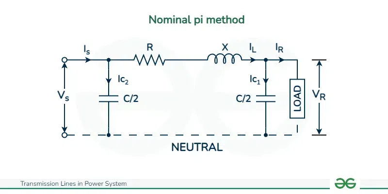
Nominal pi method
Phasor Diagram of Nominal Pi method can be given as
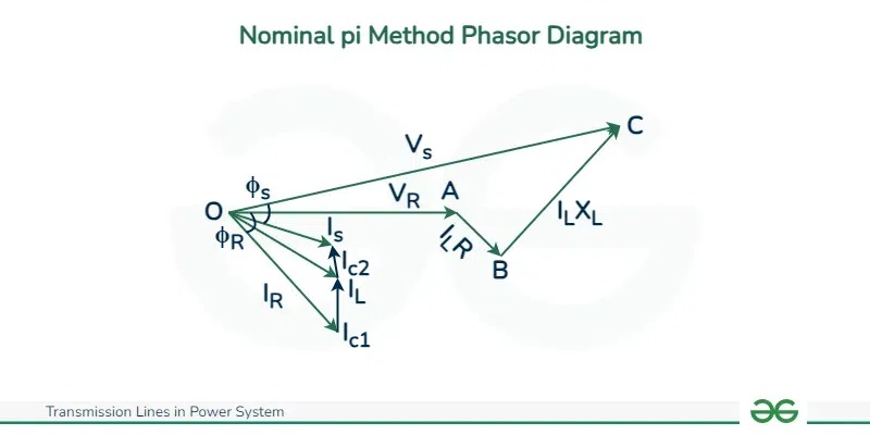
Nominal pi Method Phasor Diagram
Advantages of Nominal Pi Model
- It is the most used model in medium transmission line making it easy to understand.
- It is very accurate model.
- It is very simple and manageable.
Disadvantages of Nominal Pi Model
- If the line length is more then the approximate value will decrease and not be much accurate.
- Due to this method the exact behavior of the line is not taken which is not proper.
Calculation in Nominal Pi Method
[Tex]A=D=1+\frac{ZY}{2}
[/Tex]
[Tex]B=Z[/Tex]
[Tex]C=Y(1+\frac{ZY}{4})[/Tex]
Calculation of Sending end voltage and current
[Tex]I_R[/Tex] = load current per phase
R = resistance per phase
C = capacitance per phase
[Tex]X_L[/Tex] = inductive reactance per phase
[Tex]cos\phi_R[/Tex] = receiving end power factor (lagging)
[Tex]V_S[/Tex] = sending end voltage per phase
[Tex]\vec{V_R}=V_R+j0[/Tex]
[Tex]\vec{I_R} = I_R(cos\phi_R – jsin\phi_R)[/Tex]
line current is [Tex]\vec{I_L}=\vec{I_R}+\vec{I_{c1}}[/Tex]
sending end voltage [Tex]\vec{V_S}=\vec{V_R}+\vec{I_L}\vec{Z}=\vec{V_R}+\vec{I_L}(R+jX_L)[/Tex]
Charging the current at sending end –
[Tex]\vec{I_{c2}}=j\omega (\frac{C}{2}\vec{V_S})[/Tex]
[Tex]j\pi fC\vec{V_S}[/Tex]
Sending end current,
[Tex]\vec{I_S}=\vec{I_L}+\vec{I_{c2}}[/Tex]
Nominal T Method
It is the method in the medium transmission line which is used to analyze the medium transmission lines on the basis of its parameters like resistance, inductance and capacitance in the form of T shape. All the parameters are stored in the middle point of the model.

Nominal T Method
Phasor Diagram of Nominal T Method can be given as

Nominal T Method Phasor Diagam
Advantages of Nominal T Method
- It is less complex as compared to the pi model which is helpful.
- It is also accurate.
- It is more effective way.
Disadvantages of Nominal T Method
- For the more high voltage medium transmission line the Nominal T Method is not used more as it becomes less accurate.
- It does not have distributed capacitance in the model.
Calculation of Nominal T Method
[Tex]A=D=1+\frac{ZY}{2}[/Tex]
[Tex]B=Z(1+\frac{ZY}{4})[/Tex]
[Tex]C=Y[/Tex]
Calculation of Sending end voltage and current –
[Tex]I_R [/Tex]= load current per phase
[Tex]X_L[/Tex] = inductive reactance per phase
[Tex]cos\phi _R[/Tex] = receiving end power (lagging)
R = resistance per phase
C = capacitance per phase
[Tex]V_S[/Tex] = sending end voltage per phase
[Tex]V_1[/Tex] = voltage across capacitor
Now,
receiving end voltage,
[Tex]\vec{V_R} =V_R+j0[/Tex]
load current is [Tex]\vec{I_R} =I_Rcos\phi_R-jsin\phi_R[/Tex]
Voltage across C is,
[Tex]\vec{V_1} =V_R+I_R(cos\phi_R-jsin\phi_R)(\frac{R}{2}+j\frac{X_L}{2})[/Tex]
Therefore we get ,
capacitive current as – [Tex]\vec{I_C}=j\omega C\vec{V_1}=j2\pi fC\vec{V_1} [/Tex]
Sending end current as – [Tex]\vec{I_S} = \vec{I_R}+\vec{I_C}[/Tex]
Sending end voltage as – [Tex]\vec{V_S}=\vec{V_1}+\vec{I_S}\frac{\vec{Z}}{2}=\vec{V_1}+\vec{I_S}(\frac{R}{2}+j\frac{X_L}{2})[/Tex]
End Condenser Method
It is also a method to analyze the performance of medium transmission line. It is the most easier and quicker way to analyze the performance. It is very simple method as compared to both nominal pi and nominal t method. In this method the whole capacitance is focused at a single point, most of the time at receiving end.
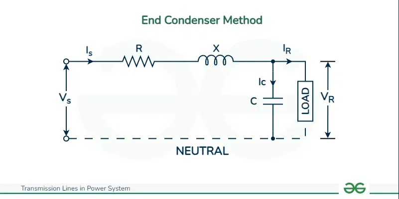
End Condenser Method
Phasor Diagram for End Condenser can be given as

Phasor Diagram of End Condenser Method
Advantages of End Condenser Method
- It is the most simple method among all three.
- It is suitable for quick estimation of the voltage regulation and power transfer.
Disadvantages of End Condenser Method
- As it mostly focuses on receiving end the capacitance effect is overestimated.
- It is not much accurate.
Calculation of End Condenser Method
[Tex]V_R=V_R+j0[/Tex]
Load current [Tex]I_R=I_R\phi_R[/Tex] (lagging)
[Tex]=I_R(cos\phi_R-jsin\phi_R)[/Tex]
Now shunt capacitor is [Tex]I_C=jl_C[/Tex]
But we know [Tex]I_C=V_R/(1/\omega C)=\omega CV_R[/Tex]
[Tex]I_C=j\omega CV_R=j2\pi fCV_R[/Tex]
Now,
[Tex]I_S=I_R+I_C[/Tex]
[Tex]I_R(cos\phi_R-jsin\phi_R)+j2\pi fCV_R[/Tex]
[Tex]i_Rcos\phi_R+j(2\pi fCV_R-I_Rsin\phi_R)[/Tex]
Now we know,
[Tex]V_S=V_R+I_SR+jI_SX[/Tex]
[Tex]=V_R+I_S[R+jX][/Tex]
So we calculated sending end voltage and sending end current. Now the sending end power can also be calcluated.
The Voltage Regulation of medium line by end condenser method is –
[Tex]\%Voltage Regulation = (V_S-V_R)\times 100/V_R \%[/Tex]
Long Transmission Line
Long transmission lines are the transmission line that are having a length more than 150Km. Long transmission lines have the voltage level ranging between 115Kv to 765Kv. These lines transfer the power over thousands and thousands of Kilometers. As there length and voltage level is high so the capacitance effect taking place and cannot be neglected. So while making the equivalent circuit we consider resistance, inductance and capacitance. It is the most complex model among the three types.
Some Applications of long transmission line are
- Transmission of power from bulk generating plant to various regions.
- Interconnecting so many grids to regions.
Advantages of long transmission line
- Due to the high capacitance the power management is better.
- It can deliver more energy.
- It is more efficient.
Disadvantages of long transmission line
- Due to the resistance the voltage drop increases.
- Due to the resistance the power loss increases.
Efficiency of Transmission Line
The efficiency of Transmission line means the amount of the electrical power that is received from the receiving end that was sent from the sending end. It depends on many factors like –
- Length of the Conductor
- Voltage Level
- Material by which conductor is made up of
- Size of the conductor
- Distance
- Capacitance
- Inductance
- Resistance
Efficiency Calculation
Efficiency of Transmission line is calculated by the ratio of the receiving end [Tex]P_R[/Tex] to the sending end [Tex]P_S[/Tex]. It’s value is expressed in percentage.
[Tex]\%\eta T= \frac{P_R}{P_S}\times 100[/Tex]
The ratio of receiving end power to the sending end power of a transmission line is called as the transmission efficiency of the line.
%Transmission Efficiency [Tex]\eta T=\frac{Receiving end power}{Sending end power} \times 100 [/Tex]
[Tex]=\frac{V_RI_Rcos\phi R}{V_SI_Scos\phi R} \times 100[/Tex]
Here, [Tex]V_R,I_R and cos\phi_R[/Tex] are at receiving end voltage, current and power factor while [Tex]V_S,I_S and cos\phi _S [/Tex]
How to Improve Efficiency
There are many ways in which we can improve efficiency like
- Use high voltage transmission lines.
- Lessen the length of the transmission line.
- We should manage the power properly that means reactive power management should be there.
Voltage Regulation of Transmission Line
Voltage Regulation means the power to maintain the required voltage level at the receiving end without changing the load or the distance on the conductor. It is expressed in percentage in the formula and denoted as [Tex]\% VR
[/Tex]
[Tex]\%VR=\frac{V_S-V_R}{V_R}\times100[/Tex]
Here,
[Tex]V_S
[/Tex]is sending end voltage and,
[Tex]V_R[/Tex] is receiving end voltage
Voltage Regulation is very important aspect in transmission lines. By properly understanding the factors that affect the voltage drops and using proper regulation techniques we can make good use of transmission lines.
Factors Affecting Voltage Regulation
- Line Resistance : If the Resistance is more then the voltage drop is more that means the voltage regulation is not proper.
- Power Factor : If the Power Factor is lagging then the voltage regulation is not proper.
- Line Length : Due to long line, voltage regulation is bad.
How to improve Voltage Regulation
- We can use high voltage transmission line.
- We can use capacitor banks which will help in improving voltage regulation.
- We can use tap changers on the transformers to adjust the voltage ratio.
Expression of Voltage Regulation
Voltage Regulation can be called as the measure of the voltage dropped along the length of the transmission line that means from sending end to the receiving end.
At no load condition the sending end voltage is equal to receiving end.
[Tex]V_R=V_S[/Tex]
Voltage Regulation of Transformer for Lagging Power Factor
Now, from the Phasor Diagram we can tell that
[Tex]OC=OA+AB+BC
[/Tex]
[Tex]OA=V_2[/Tex]
[Tex]AB=AEcos\theta _2 = I_2R_2cos\theta _2[/Tex] and
[Tex]BC=DE sin\theta _2=I_2X_2sin\theta _2[/Tex]
As the angle between OC and OD is very small so we can ignore it and we get
[Tex]E_2=OC=V_2+I_2R_2cos\theta _2+I_2X_2sin\theta_2[/Tex]
Now we get voltage regulation at lagging load as,
[Tex]\frac{I_2R_2cos\theta_2+I_2X_2sin\theta_2}{V_2} \times 100[/Tex] (This value will be in percent)
Voltage Regulation of Transformer for Leading Power Factor
Now, from the Phasor Diagram we can tell that
[Tex]OC=OA+AB-BC[/Tex]
[Tex]OA=V_2[/Tex]
[Tex]AB=AEcos\theta_2=I_2R_2cos\theta_2[/Tex]
[Tex]BC=DEsin\theta_2=I_2X_2sin\theta_2[/Tex]
As the angle between OC and OD is very small so we can ignore it and we get
[Tex]E_2=OC=V_2+I_2R_2cos\theta_2-I_2X_2sin\theta_2[/Tex]
Therefore voltage regulation for leading power factor is –
[Tex]\frac{I_2R_2cos\theta_2-I_2X_2sin\theta_2}{V_2} \times 100[/Tex] (In percent)
Load Power Factor on Efficiency of Transmission Lines
Load power factor has an impact on the efficiency of the transmission lines. The reasons are as folllows-
Power Factor and Current
Power factor [Tex]cos\phi[/Tex] is the ratio of the actual power P to the total apparent power S flowing in the circuit. So maintaining a good load power factor is very important for increasing the efficiency of the transmission line.
So, Formula can be Written as
Power Factor [Tex]cos\phi=\frac{P}{S}[/Tex]
Impact of Load Power Factor on Transmission Line
- The current in the line increases as the power factor is less.
- The [Tex]I^2R[/Tex] losses are increased.
- The Efficiency is reduced.
By this we know that by understanding the relationship between the load power factor and the efficiency of transmission line we can optimize the power in the line and we can have more efficiency.
Calculation of Power and Current
%Voltage Regulation is given as when a load lagging power factor is connected then –
[Tex]\% Voltage Regulation=\frac{IRcos\phi_R}{V_R}\times100\%……(1)[/Tex]
Here R is receiving end quantities
%Voltage Regulation is given as when a load leading power factor is connected then –
[Tex]\%Voltage Regulation=\frac{IRcos\phi_R}{V_R}\times100\%…….(2)[/Tex]
Now we can tell the effect of load power factor on transmission efficiency is-
For single phase transmission line –
[Tex]P=V_RIcos\phi_R[/Tex]
Now,
[Tex]I=\frac{P}{V_Rcos\phi_R}……(3)[/Tex]
For three phase transmission line –
[Tex]P=3V_RIcos\phi_R[/Tex]
Now we know,
[Tex]I=\frac{P}{3V_Rcos\phi_R}[/Tex]…….(4)
Now from equation 3 and 4 we can see that for a power P to transmitted and receiving end voltage the load current is inversely proportional to the power factor of the load.
So as the load power factor decreases the load current and the power losses in the transmission line are increased.
Parameters of Transmission Lines
There are four main parameters of transmission lines –
- Resistance (R) : It is the ability to oppose the flow of electric current in the electric circuit. It is measured in ohms [Tex]\omega[/Tex]. Resistance also helps in power loss in the transmission line.
- Inductance(L) : It is called as the introduction of current in a coil caused by the interference of the flux of the same coil or one near it. It is of two types – mutual inductance and self inductance. It is measured in Henry (H).
- Capacitance(I) : It is the power of the circuit to store energy in the form of an electrical charge. Basically we can call them as energy storing devices which is available in many shapes and sizes.
- Shunt Conductance(G) : Shunt conductance is caused due to leakage currents flowing across insulators and air. It is measured in siemens(S) per unit length. Most of the time in overhead transmission line it is neglected as it is very low. But in underground transmission line it is measured.
Applications of Transmission Lines
The main use of Transmission Lines is to transfer the electricity over long distances. They carry so much amount of power from one region to another. Their main applications are –
- Bulk Power Transmission: They provide electric power in much big amount for the resources like hydroelectric dams , solar farms , etc.
- Interconnecting power grids: The Transmission Lines helps to connect so many power grids with each other. This helps in sharing electricity between different countries.
- Connecting Substations: Transmission Lines help in connecting different substations to each other, they can be local or in different cities which helps in faster power transferring.
- Distribution: Last and the most important aspect of transmission lines are that it helps in distribution of the electric power from one place to another helping many businesses and households.
Properties of Transmission Lines
Some properties of Transmission Lines
- Type of Conductors : There are two types they are overhead conductors and underground conductors made of Aluminium or Steel and Insulated materials respectively.
- Number of Conductors : Transmission Lines mainly has three conductors for three phase power transmission.
- Size of the Conductor : The size of the conductor affects its resistance and current carrying capacity.
- Type of Support : The type of tower is also important and the material from which they are made.
- Length : The length of the transmission line also plays an important role in the electrical behavior.
- Voltage Level : Transmission Line operate at different voltage levels.
Protection of Transmission Line
Protection of Transmission Line is also the most important factor that affects the distribution of electrical power. There are various ways to protect the transmission line
- Over Current Protection : This is the most used technique to protect the transmission line. In this method it automatically detects the high currents exceeding the set amount, by which we know there is a fault. After this the relays get tripped and further damage is not happened.
- Distance Protection : In this type of protection both resistance and reactance is used that means impedance is used to measure the fault. It is mostly used fir long transmission lines where it is hard to tell where the fault is.
- Ground Fault Protection : In this method we detect faults if the current leaks from the ground.
- Protective Relays : By installing Protective Relays, our system is protected from major faults. They are helpful to us as they are used for monitoring all the crucial processes.
- Regular Maintenance : We indeed know that all the protection provided from machines are good, but it will be at its best when there will be regular maintenance and inspection by workers. This will help the system to be stable.
Conclusion
In conclusion we could say that transmission lines play a huge role in delivering electricity from one region to other over a long distances. They also make an impact on the environment. Due to energy loss to minimize it high voltage is used. Different types of Transmission lines have different types of impact depending on various factors. There are also many ways to protect the transmission lines so that no fault occurs in the system.
Transmission Lines in Power System – FAQs
Why is high voltage used?
High voltages are used in transmission lines as it reduces the energy loss.
What is the future of Transmission Lines?
In recent times the Transmission Lines are integrated with new smart grid technologies and many new hot technologies are being added in the system.
What is the Environmental Impact caused by Transmission Lines?
Different type of transmission line makes different type of impact on the environment.
Share your thoughts in the comments
Please Login to comment...