Resonance in electric circuits is a phenomenon that plays a vital role in changing the behavior of circuits and the transmission of electrical signals. Resonance plays a crucial role in various applications ranging from tuning radio frequencies to enhancing power transfer in electrical systems. This function takes place at a particular constant frequency, at the moment when impedance and reactance cancel out each other. In this article, we will go through the resonance in electric circuits and how it affects them, the types and applications which are widely used in many devices.
Resonance
Resonance is a condition that occurs when the inductive reactance (XL) and capacitive reactance (XC) in an AC circuit cancel each other out. The net reactance becomes zero, leading to an increase in current flow and voltage amplitude. The alignment of reactive elements causes the circuit to be more responsive to the applied AC frequency.
Definition of Resonance
“A phenomenon in which an external force or a vibrating system forces another system around it to vibrate with greater amplitude at a specified frequency of operation.”
Key Components in Resonance
- Inductive Reactance (XL): Inductive Reactance is the opposition that an inductor presents to an alternating current. It is directly proportional to the frequency of the AC signal. It is represented by (XL) and measured in ohms (Ω). It is mostly low for lower frequencies and high for higher frequencies. However it is negligible for steady DC current. The inductive reactance formula is given as follows: XL = 2πfL .As the frequency increases the inductive reactance also increases.
- Capacitive Reactance (XC): A capacitor is a device used to store electrical energy. The capacitance of a capacitor determines the amount of charging a capacitor can achieve. The measure of the opposition to alternating current by the capacitor is called Capacitive Reactance. It is the resistance of a circuit element to changes in current or voltage. Its standard unit of measurement ohms (Ω). It is represented by the symbol Xc. It is inversely proportional to the frequency of the AC signal. As the frequency increases the capacitive reactance decreases. The capacitive reactance formula is given as follows: XC = 1/2πfC
- Resonant Frequency (f0): The frequency at which the inductive and capacitive reactances are equal in magnitude but opposite in phase resulting in cancellation. It can be calculated using the formula:
f0=1/2π√(LC)
where L is the inductance and C is the capacitance.
- Resonant frequency in electronics is expressed when a circuit exhibits a maximum oscillatory response at a specific frequency. This is observed for a circuit that consists of an inductor and capacitor.
Effect of Resonance
We all have seen that the singer breaks a glass with their loud voice this happens due to Resonance. The frequency produced by an object can excite any vibration that occurs near the same frequency. The Resonance can also damage high buildings and bridges. The earthquake also occurs due to the Resonance and if it has the same frequency as the building, it causes some damage. So the Resonance cannot be ignored before constructing any buildings or bridges.
It also increases current and voltage due to which the impedance of the circuit becomes purely resistive which means there is no opposition to the flow of current. This leads to a maximum flow of current or voltage across the circuit depending on the configuration. If excessive voltage or current is applied at the resonant frequency the components can overheat and damage the circuit. As a result inductive and capacitive system components draw overcurrent.
Characteristics Of Resonance
- Stability: Stability is important for maintaining the desired resonant frequency and response characteristics under varying loads and environmental conditions.
- Current change: The current flowing through the circuit changes depending on the type of resonance.
- Frequency Selectivity: Resonance circuits are highly selective at resonant frequency the circuit exhibits maximum impedance (in a series resonance circuit) or minimum impedance (in a parallel resonance circuit), resulting in a sharp peak in the circuit’s response. The sharp peak allows resonance circuits to filter out unwanted frequencies.
- Voltage change: Individual components experience voltages higher than the source voltage at resonance.
- Phase Shift: In series resonance circuit voltage and current are in phase while in a parallel resonance circuit they are 180 degrees out of phase.
Types Of Resonance
- Series Resonance
- Parallel Resonance
Now we will discuss each type of resonance one by one in detail:
Series Resonance
In a series resonance circuit, the inductor (L) and capacitor (C) are connected in series, along with a resistor (R). The resonant frequency (f₀) is the frequency at which the inductive and capacitive reactance cancel each other out, resulting in a minimum impedance. During this point the circuit becomes highly responsive to the applied frequency.
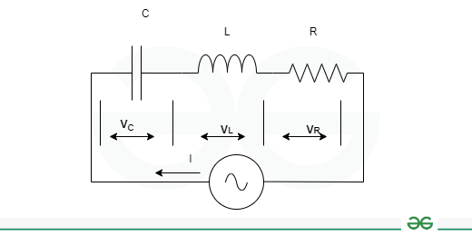
Series Resonance Circuit
In this circuit, the voltage across the inductor and capacitor is equal, i.e.
VL=VC
At resonance frequency,
XL=XC
Where XL is the inductive reactance and XC is the capacitive reactance. Voltage can be obtain by applying KVL to the series RLC circuit.
V=VR+VL+VC
If I is the current flowing through the circuit, then
VR=IR
VL=IXL
VC=IXC
Therefore, the voltage equation can be written as
V=IR+IXL+IXC
Also, the reactance XL and Xc are given by,
XL=jωL=j2πfL
XC=1/jωC=1/j2πfL
Therefore,
V=I[R+j(ωL-1/ωC]
Hence, the above equation is in the form of V = IZ, where Z is called the impedance of the circuit i.e.
Z=R+j(ωL-1/ωC)
Electrical Quantities and Parameters at Series Resonance
- Resonance Frequency: The supply frequency at which the inductive reactance and capacitive reactance become equal to each other is called the resonance frequency. Resonant frequency is expressed when a circuit exhibits a maximum oscillatory response at a specific frequency. This is observed for a circuit that consists of an inductor and capacitor. It is denoted by fr.
At series resonance,
XL=XC
ωL=1/ωC
Here, ω = ωr, angular resonance frequency.
ωr=1/√LC
The linear resonance frequency will be,
fr=1/2π√(LC)
- Impedance: Impedance is the total opposition that the circuit presents to the flow of alternating current. It is a combination of resistance and reactance due to the presence of resistive, capacitive, and inductive elements within the circuit. The impedance of a series RLC circuit is given by,
Z=R+j(XL-Xc)
At series resonance,
XL=XC
Therefore,
Z=R
- Current: Current is the flow of electric charge through the circuit elements in a single path. In a series circuit all components like resistors, capacitors, and inductors are connected end-to-end so the same current flows through each component. At series resonance: XL = XC
Then,
I=V/R
The circuit draws current from the source only due to the resistance of the circuit which is the maximum value of the current that can flow through the series RLC circuit. The figure shows the relation between the series resonance circuit’s current, impedance, and resonance frequency.
.png)
Series Resonance
- Quality Factor: The quality factor of a series RLC circuit is defined as a ratio of energy stored in each cycle to the energy dissipated in each cycle, i.e.
Q=1/R*√L/C
Parallel Resonance
In a parallel resonance circuit, the inductor (L) and capacitor (C) are connected in parallel, with a resistor (R) typically in series with the inductor. At the resonant frequency (f₀), the impedance of the inductor and capacitor cancel each other out, resulting in a sharp increase in current flow through the circuit.

Parallel Resonance
The resonance occurs when the instantaneous values of currents IL and IC are equal and opposite to each other.
Applying KCL to this parallel RLC circuit we get,
I=IR+IL+IC
According to Ohm’s law,
IR=V/R; IL=V/jXL; IC=V/(-jXC)
Therefore, the total circuit current is given by,
I=V/R+V/jXL-V/(jXC)
Hence, I=VY
Where,
Y=1/R+j(1/XC-1/XL)
Condition of Parallel Resonance
XL=XC
Electrical Quantities at Parallel Resonance
- Resonance Frequency: The resonance frequency of a parallel resonance circuit is the value of the supply frequency where the inductive reactance XL becomes equal to the capacitive reactance XC i.e.
XL=XC
2πfL=1/2πfC
f2=1/4π2LC
fr=1/2π√LC
Also,
ωr=1/√LC
The resonant frequency of a parallel RLC circuit depends on the value of capacitance and inductance.
- Impedance: At resonance the value of circuits admittance is minimum which disrupts the flow of electric current.
.png)
Parallel Resonance
The impedance of the circuit is maximum at resonance and the circuit draws minimum current.
Z=R
- Admittance: Admittance is the measuring ability of the current through a device or circuit. This is the inverse of impedance which is similar to how conductance is related to resistance. The SI unit of admittance is the siemens represented by symbol S.
Admittance is given by: Y=1/R+j(1/XC-1/XL)
At resonance: XL=XC
Putting it in the admittance equation we get
Y=1/R
At resonance the admittance Y being equal to the resistance reciprocal.
Voltage: Voltage refers to the potential difference across each branch of the circuit. In Parallel circuit the voltage remains the same across each branch.
At parallel resonance,
XC=XL
Therefore,
I=VR
V=IR
At parallel resonance the voltage across each element will be equal to the voltage across the resistance. This is the maximum value of the voltage that appears across each element.
- Current: Current is the flow of electric charge through each individual branch of the circuit. In parallel circuit total current splits among the various branches based on their individual resistances or impedances. The circuit current I at parallel resonant condition is given by,
I=IR
- Quality Factor: At parallel resonance,
fr=1/2π√LC
Q=R√C/L
- Bandwidth: The difference in upper frequency and lower frequency denotes the bandwidth of the parallel resonance circuit. The power dissipation at the upper and lower frequencies is half of the full power dissipated at the resonance frequency fr.
The bandwidth of the parallel resonance circuit is expressed by the following formula.
BW=fupper-flower
BW=fr/Q
Differentiate Between Series and Parallel Resonance
|
Series Resonance
|
Parallel Resonance
|
|
Series Resonance circuit is an acceptor circuit.
|
Parallel Resonance circuit is an rejecter circuit.
|
|
At resonance the impedance is a maximum.
|
At resonance the impedance is maximum nearly equal to infinity.
|
|
Current at resonance is maximum = V/R.
|
Current at resonance is minimum = V/(L/CR).
|
|
Power factor is unity.
|
Power factor is unity.
|
|
Series circuit magnifies voltage.
|
Parallel circuit magnifies current
|
|
The series resonance is widely used in tuning, oscillator circuits, voltage amplifiers, high frequency filters, etc.
|
The parallel resonance is used in current amplifiers, induction heating, filters, radio-frequency amplifiers, etc.
|
Application of Resonance
It has some vast practical applications in the electrical engineering field. Below are five applications of resonance in RLC circuits:
- Used for Voltage multiplier
- Used to filter a signal by blocking some frequencies and passing others.
- Used for Pulse discharge circuits
- Used in different types of oscillator circuit.
- These are used in the tuning circuits of analogue radios.
Advantages of Resonance
- Selective tuning: Filtering out unwanted signals and focusing on the desired frequency band in communication systems.
- Amplification: Resonance circuits provide strong amplification to signals resulting in increased signal power. It is used in the applications communication systems.
- Impedance Matching: Resonance circuits are also used for impedance matching purposes ensuring maximum power transfer between the source and load. It is used in antennas and transmission lines.
- Energy Efficiency: Resonance circuits can store and transfer energy efficiently between the inductive and capacitive elements. The applications of energy efficiency are wireless power transfer systems and energy storage.
Disadvantages of Resonance
- Bulkiness: The inductive and capacitive components can be bulky and heavy limiting the downsize of resonant circuits.
- Narrow Bandwidth: Resonance circuits sometimes have a narrow bandwidth which means that they are effective for a limited range of frequencies. This limitation can restrict their capability in applications requiring broader frequency coverage.
- Complex Design Requirements: Designing resonance circuits with specific performance characteristics can be complex and require detailed analysis. Achieving desired resonance properties such as bandwidth and Q factor often necessitates careful consideration of circuit and component values.
Conclusion
Designing and operation of electrical circuits gets affected by resonance which allows to design efficient and accurate electronic systems for various applications like radio communication and medical diagnostics. It is also used in the working principle of music instruments as it allows us to hear and communicate with one another. It allows engineers to optimize circuit performance for specific applications such as communication systems, filtering, amplification and power transfer. Resonance is a fundamental concept that finds applications in a wide range of fields from telecommunications to medical imaging. The study of resonance will lead to innovations in the field of electronics in future.
FAQs on Resonance
What do you mean by Resonance?
Resonance is phenomena of vibrating an object at larger amplitude when its frequency matches with an externally vibrating object.
How does resonance cause an earthquake?
The waves produced during the earthquake have the same frequency as the building. Due to this the building starts to vibrate with enormous amplitude, and this causes the building to collapse.
What do you mean by resonance frequency?
frequency at which an object vibrates with the highest amplitude is called its Resonant Frequency.
Share your thoughts in the comments
Please Login to comment...