In 1831, Michael Faraday, a British physicist, devised the electromagnetic generator. The primary function of this device is to convert mechanical energy to electrical energy. There are several types of mechanical energy sources available, including hand cranks, internal combustion engines, water turbines, and gas and steam turbines. The generator provides capacity for all electrical power networks. An electric motor should be able to perform the generator’s converse function. The basic purpose of the motor is to convert electrical energy into mechanical energy. Generators and motors have many properties.
What is a DC Generator?
An electromechanical energy conversion device known as a DC generator uses electromagnetic principles to convert mechanical power into DC electrical power. According to the electromagnetic induction theory, an EMF is induced in a conductor when the magnetic flux connecting them changes. This is how a DC generator works. In a DC generator, there are two windings: the field and the armature.
The EMF made in the armature Winding of a DC generator is rotating and is switched over completely to coordinate voltage by a commutator introduced on the generator’s shaft. A DC generator’s armature winding is on the rotor, while the field winding is on the stator.
Construction of a DC Generator
Below is a schematic representation of a DC generator :
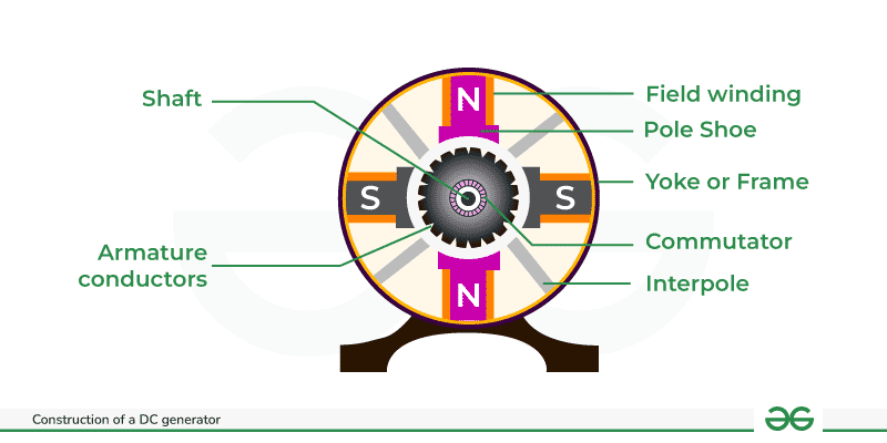
Construction of a DC generator
Components of DC Generator
Components of DC Generator are given below :
- Yoke
- Magnetic Field System
- Armature Core
- Armature Winding
- Commutator
- DC Generator Commutator Function
- Shaft
- Pole Shoe
- Poles
- Bearings
Yoke
The outside frame of a DC generator is a hollow cylinder made of cast or rolled steel, known as a yoke. The yoke provides the following two objectives.
- It supports the field pole core and serves as a protective cover for the machine.
- It offers a channel for the magnetic flux produced by the field coil.
Magnetic Field System
A DC generator’s magnetic field system serves as its stationary component. It generates the primary magnetic flux in the generator. It is made up of a large number of pole cores fastened to the yoke with field winding coiled around the pole core. The field arrangement of a DC generator features prominent poles, such as poles that thrust inwards, and each pole core has a post shoe with a curved surface. The shaft shoe has two objectives.
- It provides support for the field coils.
- It lowers the reluctance of a magnetic circuit by expanding its cross-sectional area.
To prevent eddy current loss, the pole cores are constructed of thin, insulated sheet steel laminations. The field coils are linked in series to create alternating north and south poles in the rotating direction as the current flows through them.
Armature Core
The armature core of a DC generator is positioned on a shaft and pivots between the field poles. It features slots on its exterior surface where the armature conductors are installed. The armature core is made up of soft iron laminations that are isolated from one another and securely Attached together. In big machines, the laminations are keyed, but in tiny machines, they are keyed directly to the shaft. The laminated armature core helps to decrease eddy current losses.
Armature Winding
The insulated conductors are inserted into the slots of the armature core. The wires are properly connected. The linked arrangement of conductors is known as armature winding. There are two types of armature windings used: wave winding and lap winding.
Commutator
A commutator is a mechanical rectifier that converts the alternating magnetic field of the armature winding into a direct voltage that runs through the load terminals. The commutator is constructed up of wedge-shaped copper segments that are isolated from one another and the shaft by mica sheets. Each commutator segment is connected to one of the armature coil’s ends.
DC Generator Commutator Function
The basic purpose of the commutator is to convert DC to AC. It functions as a reversing switch, and its purpose in the generator is explained below.
The electromagnetic field produced within the generator’s armature coil alternates, leading to an alternating current flowing within the armature coil.This current may be reversed through the commutator at the precise moment that the armature coil crosses the magnetic unbiased axis. As a result, the load develops a DC or unidirectional current.
The commutator ensures that the current flowing from the generator continues in the same direction indefinitely. By moving along the commutator, the brushes create high-quality electrical connections between the generator and the load.
Shaft
The shaft is a key component of a DC machine because it produces torque, which causes rotation. It is constructed of mild steel and has the highest breaking strength. The shaft is a component of a DC generator that influences the generator’s ability to transport mechanical energy. The shaft is keyed to the commutator, cooling fan, armature center, and other spinning components.
Pole Shoe
A pole shoe is a plate composed of iron or steel that spreads magnetic flux and prevents field coils from falling.
Poles
Poles help maintain the field windings in excellent shape. These windings are generally coiled on poles and linked in a certain order to the armature windings. As a result, the posts attach the welding procedure to the yoke using screws.
Bearings
Bearings are used in a system to ensure that the various parts of a DC machine move smoothly. The friction between the machine’s spinning and stationary elements is reduced with the aid of course. As a result, the system’s components require less frequent greasing and will last longer. Roller bearings and ball bearings are the two most popular types of bearings used in dc generators.
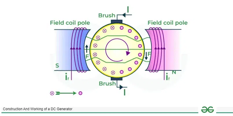
Workings of a DC Generator
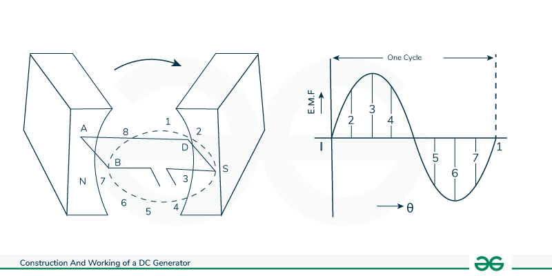
Consider a single loop DC generator (as seen in the diagram), in which a single turn loop ‘ABCD’ rotates clockwise in a uniform magnetic field at constant speed. As the loop rotates, the magnetic flux between the coil sides ‘AB’ and ‘CD’ changes continually. This change in flux linkage causes an EMF to be induced in both coil sides, and the induced EMF on one coil side is added to the induced EMF on the other.
Workings of a DC Generator
The EMF produced by a DC generator may be explained as follows:
- When the loop is at position 1, no EMF is produced since the coil sides move in parallel with the magnetic flux.
- When the loop is in position 2, the loop sides move in the direction of the attracting motion, generating a tiny EMF.
- When the loop is at place 3, the coil sides move at the right point to the attractive transition, resulting in the highest EMF.
- When the loop is in position 4, the coil sides cut the attractive transition at a point, resulting in a lower EMF in the coil sides.
- When the loop is at place 5, there is no motion coupling with the coil side, and the movement is aligned with the attractive transition. Consequently, no EMF is produced in the coil.
- At position 6, the coil sides move beneath an inverse extremity post, switching the extremity of the generated EMF. The most intense EMF will be produced toward this route at position-7, and zero at position-1. This cycle repeats for each coil turn.
It is evident that the produced EMF is a spinning one. It is because any coil side (for example, AB) has EMF in one direction when impacted by an N-pole and in the opposite direction when affected by an S-pole. As a result, when a load is attached to the generator’s terminals, alternating current flows through it. Currently, using a commutator, the alternating emf created in the loop may be converted into direct voltage.
Types of DC Generators
There are three techniques of excitation, and hence three primary types of DC generators:
- Permanent Magnet DC Generators – Field coils energized by permanent magnets
- Separately stimulated DC Generators: Field coils stimulated by an external source.
- Self-excited DC generators have field coils that are stimulated by the generator itself.
These generators are further classified based on their field coil location. They are:
- Series Generators
- Shunt Generators
- Compound Generators
Permanent Magnet DC Generator
A permanent magnet DC generator is one that generates flux in a magnetic circuit using permanent magnets.
Permanent Magnet DC Generator
It consists of an armature and one or more permanent magnets positioned around it. This sort of DC generator does not create a lot of power.
As a result, industrial applications seldom employ them. They are commonly employed in tiny applications, like as dynamos in bikes.
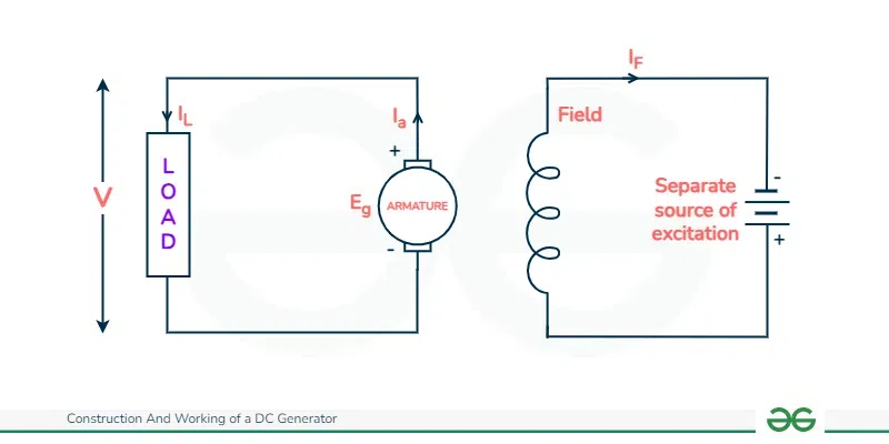
Separately Excited DC Generator
These are generators with field magnets powered by an external DC source, such as a battery.
The circuit diagram for a separate DC generator is given in the figure below.
- Ia = armature current.
- IL = Load Current
- V = terminal voltage.
- Eg = generated EMF (Electromagnetic Force).
Separately Excited DC Generator
Let
Ia = IL=I
The voltage across the load ,
V = I. Ra
The power created is equal to
Pg = Eg x I
The power provided to an external load is calculated using the equation
PL=V x I
DC Generators with Self-Excitation
Self-excited DC generators will have field magnets that are powered by the current supplied by themselves. In these devices, the field coils and armature are linked internally.
Because of residual magnetism, there is always flux at the poles. When the armature is pivoted, some EMF is generated. Thus, some induced current is generated. As the pole flux increases, so does the armature EMF, causing the current to flow faster through the field. This increased field current rises armature EMF.
Self-excited DC generators can be characterized as follows based on where the field coils are:
- Series Generators
- Shunt Generators
- Compound Generators
Series Generators
In these generators, the field windings are linked in series with the armature conductors, as seen in the diagram below.
The whole current goes through both the field coils and the load. As a series field winding carries full load current, it is constructed with a few rounds of thick wire. As a result, the series field winding has an extremely low electrical resistance of almost 0.5.
Here:
- Rsc represents series winding resistance.
- Isc = series field current.
- Ra = Armature resistance.
- Ia = armature current.
- IL = Load Current
- V = terminal voltage.
- Eg = generated EMF.
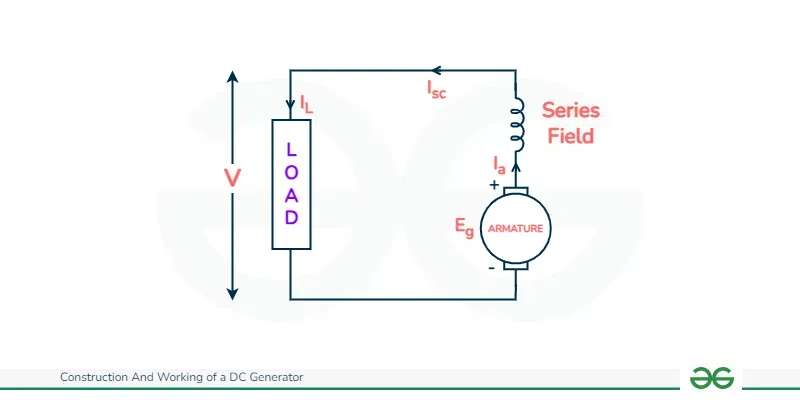
Series Generators Connection Diagram
The equation becomes
Ia = Isc = IL = I
Voltage across the load equals
V = Eg – I (Ia x Ra)
The power generated is equivalent to:
Pg = Eg x I.
The power given to the load is equal to:
PL = V x I
Shunt DC Generators
In these types of DC generators, the field windings are linked in parallel with the armature conductors, as indicated in the picture below. In shunt generators, the voltage in the field winding is identical to the voltage across the terminal.
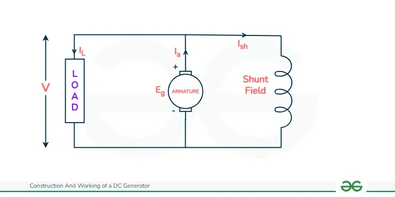
Shunt DC generators. Connection Diagram
Here:
- Rsh = Shunt winding resistance.
- Ish = current flowing through the shunt field.
- Ra = Armature resistance.
- Ia = armature current.
- IL = Load Current
- V = terminal voltage.
- Eg = generated EMF.
Here, the armature current Ia is divided into two sections: the shunt field current Ish and the load current IL.
So,
Ia = Ish + IL
When IL is at its maximum, the effective power throughout the load is at its peak. In this approach, it is necessary to keep the shunt field current as low as feasible. To get the optimal EMF, the shunt field winding resistance is often kept high (100 Ω) with a large number of turns.
The shunt field current is equal to
Ish = V/Rsh.
Voltage across the load equals
V = Eg – Ia Ra.
The power generated is equivalent to:
Pg = Eg x Ia.
The power given to the load is equal to:
PL = V x IL.
Compound DC Generator
In series wound generators, the result voltage is directly proportional to the load current. In shunt wound generators, the result voltage does not correlate to the load current.
A combination of these two types of generators can overcome the drawbacks of each. This set of windings is known as a compound DC generator.
Compound generators use both series and shunt field windings. One winding is connected in series with the armature, while the other is connected in parallel up with the armature. These DC generators may be classified into two types: short shunt compound generators and long shunt compound generators.
Short-Shunt Compound DC Generator
Short Shunt Compound DC Generators use the shunt field winding in parallel with the armature winding, as seen in the picture below. The series field current is equal to
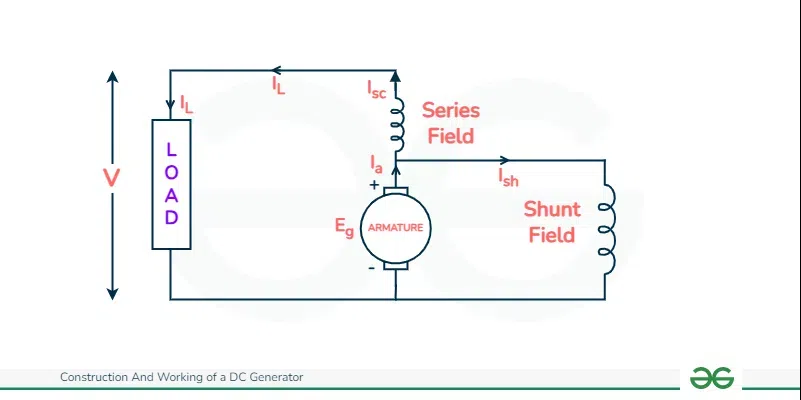
Short-Shunt Compound DC Generator Circuit Diagram
Isc = IL.
The shunt field current is equal to
Ish = (V + Isc Rsc)/Rsh.
Armature current is equivalent to,
Ia = Ish + IL
Voltage across the load equals
V = Eg-Ia Ra-Isc Rsc
The power generated is equivalent to:
Pg = Eg x Ia.
The power given to the load is equal to:
PL = V x IL
Long Shunt Compound DC Generator
Long Shunt Compound DC Generators are those in which the shunt field winding is parallel to both the series field and the armature winding, as seen in the picture below.
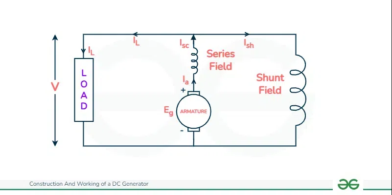
Long Shunt Compound DC Generator
The shunt field current is equal to
Ish = V/Rsh.
Armature current, Ia = series field current.
Isc = IL + Ish.
Voltage across the load equals
V = Eg-Ia Ra-Isc Rsc = Eg-Ia (Ra+Rsc)
The power generated is equivalent to:
Pg = Eg x Ia.
The power given to the load is equal to:
PL = V x IL.
In a compound generator, the shunt field is stronger than the series field. When the series field assists the shunt field, the generator is said to be commutatively compound.
However, assuming that the series field opposes the shunt field, the generator is referred to as differentially compound.
Derivation of the EMF equation for DC Generator
The derivation of the EMF equation for the DC generator involves two components.
- Induced EMF of one conductor
- Induced EMF of the Generator
Derivation for Induced EMF of a Single Armature Conductor
For one rotation of the conductor.
Let,
- Φ = Flux generated by each pole in Weber (Wb).
- P = number of poles in the DC generator.
Therefore,
- Total flux generated by all poles = Φ x P.
and,
Time required to complete one revolution = 60/N
Where,
N represents the armature conductor’s speed in revolutions per minute.
According to Faraday’s law of induction, the induced emf of the armature conductor is indicated by “e”, which is comparable to the rate of cutting the flux.
Therefore,
e = dΦ / dt, and e = total flow / time taken.
The induced EMF of a single conductor
e = Φ P/(N/60) = Φ P x (N/60) volts.
Derivation of Induced EMF for DC Generator.
Assume there are Z total number of conductors in a generator, and they are designed so that all parallel pathways are always in series.
Here,
- Z = Total number of conductors.
- A = the number of parallel pathways.
Then,
Z/A = the number of conductors connected in series.
Therefore,
Induced EMF of DC Generator
- E = the emf of one conductor multiplied by the number of conductors linked in series.
The induced emf of a direct current generator
e = ΦP x (N/60) x (Z/A) volts.
The number of parallel paths are only 2 = A.
Hence,
The induced emf of a wave type winding generator is
(ΦPN / 60) x (Z / 2) = ΦZPN / 120 Volts.
Simple lap winding generator.
Here, the number of parallel pathways equals the number of conductors in one path.
i.e. P = A
Therefore,
The induced EMF for a lap-wound generator is
Eg = (Φ Z N P) / (60 A) volts.
Losses in DC Machines
It is well-known that “Energy neither can be made nor it can be destroyed, it must be transferred from one form to another form” . A direct current (DC) machine converts mechanical energy into electrical energy. During this procedure, the entire input power is not converted into output power. Some of the input power is squandered in various forms. The types of losses may differ from one equipment to the next. As the temperature rises, these losses reduce the machine’s efficiency. There are four major forms of energy loss in a DC machine.
Copper losses
- Copper losses are winding losses that occur as the current flows through the windings. These losses occur due to resistance in the winding. In a DC machine, there are just two windings: armature and field winding.
- In this fashion, copper losses are classified into three types: armature losses, field winding losses, and brush contact resistance losses. Copper losses are proportional to the square of the current passing through the winding
Armature Copper Losses
- Armature copper loss = Ia2 Ra.
- Where Ia represents armature current and Ra represents armature resistance.
- These losses represent around 30% of the total full load losses.
Field Winding Copper Losses
- In a DC machine, the field winding copper loss =[Tex] I_f^2 R_f.[/Tex]
- where [Tex]I_f[/Tex] denotes the field resistance and [Tex]R_f[/Tex] represents the field current.
- The theoretical losses are roughly 25%, but in practice, they are constant.
Brush Contact Resistance Loss in DC Machine.
Brush contact losses are due to resistance between the outer layer of the brush and the commutator. It’s everything but losses that can be calculated individually since it’s a collection of variable losses. Overall, it contributes to both types of copper loss. As a result, they are taken into account when calculating the losses listed earlier.
Core or Iron Losses
As the iron core of the armature rotates in a magnetic field, certain losses occur in the core, known as center losses. These losses are essentially constant since machines normally run at the same pace. These losses are classified into two types: eddy current and hysteresis losses.
Hysteresis Loss in a DC Machine
Hysteresis losses occur in the armature winding as the core’s polarization reverses. When the core of an armature is subjected to a magnetic field, it undergoes a full magnetic reversal. After a full half electrical revolution, the section of the armature under the S-pole is replaced by a corresponding piece under the N-pole, and the magnetic lines are reversed to reverse the attraction within the core. The continual process of magnetic reversal in the armature consumes some energy, known as hysteresis losses. The degree of loss is determined by the iron’s grade and volume.
The frequency of magnetic reversal is f = P N / 120.
Where,
P = number of poles.
N = Speed (rpm)
Steinmetz Equation
The Steinmetz equation calculates the hysteresis loss.
Hysteresis loss (Ph) = ηB1.6max F V watts.
Where,
η = Steinmetz hysteresis coefficient.
Bmax = Maximum flux density in the armature winding.
F = Frequency of magnetic reversal.
V = armature volume in [Tex]m^3[/Tex].
Eddy Current Loss in a DC Machine
Faraday’s law of electromagnetic induction states that when an iron core rotates in a magnetic field, it generates an emf. Furthermore, as the armature spins in the attractive field, a little amount of emf is induced in the core, allowing charge to flow through the body due to the core’s conductivity. This current is unnecessary for the machine. This loss of current is known as eddy current. For DC machines, the loss is nearly always the same. It is possible that using a laminated core may limit its capabilities.
Mechanical Losses in DC Machine
Mechanical losses are those caused by the machine’s mechanical friction. These losses occur as a result of friction in the machine’s moving elements, such as bearings and brushes, as well as windage losses caused by air inside the machine’s revolving coil. These losses are typically small, accounting for just around 15% of full load losses.
Stray Losses in DC Machine
In addition to the losses mentioned above, there are a few more. These losses are referred to as “stray losses.” These various losses are due to short-circuit current in the commutating coil, flux distortion generated by the armature, and a variety of additional difficult-to-find losses. These catastrophes are difficult to decide. Regardless, they account for 1% of total load power production.
Characteristics of DC Generator
The primary mover maintains the speed of a DC generator constant. Under such circumstances, the generator’s performance is determined by the relationship between excitation, terminal voltage, and load. These relationships are visually represented as curves known as DC generator characteristics. These characteristics demonstrate the behavior of the DC generator under various load levels.
Open Circuit Characteristics or Magnetization Curve
This graph depicts the relationship between the produced EMF with no load (E0) and the field current (If) at a constant speed. It is also known as no-load saturation curve. Its form is virtually same across a wide range of DC generators, whether independently or self-excited.
Internal Characteristics
The graph depicts the relationship between produced EMF (E) on-load and armature current. Because of the influence of armature response, the magnetic flux on-load is lower than the flux at no-load. As a result, the generated EMF (E) under loaded conditions will be lower than the EMF produced (E0) with no load. As a result, the internal characteristic curves are somewhat lower than the open circuit characteristics.
External properties or load characteristics
The plot of the terminal voltage (V) and load current (IL) represents the external or load characteristics. Because of armature and series field copper losses, the terminal voltage differs from the generated voltage. As a result, the exterior characteristics curve will be lower than the internal characteristics curve by an amount equal to the voltage drop caused by machine copper losses.
Characteristics of DC Series Generator
A DC series generator has a single current that travels across the whole unit. As a result, the armature, load, and excitation currents are all the same.
Characteristics of DC Series Generator
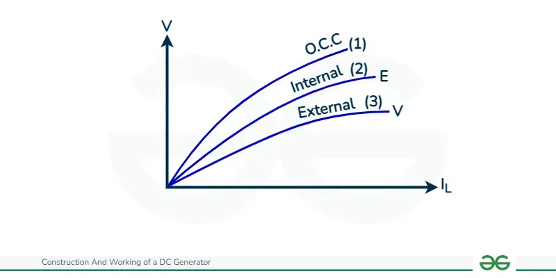
Open circuit characteristics (O.C.C)
The curve (1) in the plot depicts the O.C.C of a series DC generator. The graphic depicts the relationship between the produced EMF at no-load and field current. The O.C.C. is acquired by isolating the field winding from the machine and excited independently.
Internal Characteristics
The internal properties of a DC series generator are represented by a chart plotting the generated EMF (E) on-load against the armature current. As a result of the armature response, the magnetic flux on-load will differ from the transition at no-heap. As a result, the manufactured EMF (E) under loaded conditions will be smaller than the EMF produced (E0) with no load. The internal characteristics curve is thus placed directly below the open circuit characteristics [refer to curve (2)].
External characteristics
The plot of the load current (IL) against the terminal voltage (V) is referred to as the external characteristics or load characteristics. Because the terminal voltage is not less than the produced voltage due to armature and series field copper losses, which are provided by,
V = E-Ia (Ra + Rse)
As a result, the exterior characteristics curve will be lower than the internal characteristics curve by an amount equal to the voltage drop caused by copper losses in the machine [see curve (3)].
Characteristics of DC Shunt Generators
The armature current in a shunt generator is separated into two parts: Ish, which flows via the field winding, and IL, which is routed to the external load.
Characteristics of DC Shunt Generators
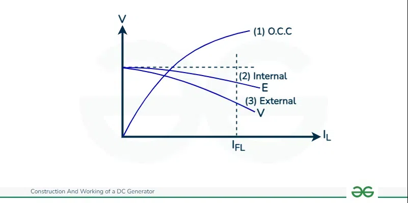
Open Circuit Characteristics
The curve (1) in the image depicts the open circuit characteristics of a DC shunt generator, which are identical to those of a series generator.
Internal characteristics
When the load is attached to the generator, the generated EMF (E) decreases due to the lower flux per shaft caused by armature response. As a result, the generated EMF under loaded conditions differs from the produced EMF with no load. As a result, the internal features decrease somewhat [see curve] (2).
External Characteristics
It shows the connection between load current (IL) and terminal voltage (V). Other names for it include load attributes and terminal characteristics.
V = E-Ia Ra.
In this case, the exterior characteristics are lower than the internal characteristics by an amount equal to the voltage drop caused by armature resistance.
External Load Characteristics of the DC Compound Generator
DC Compound Generator External or Load characteristics Compound DC generators incorporate both series and shunt fields. Compound generators are classified as short-shunt or long-shunt based on how the field winding is connected to the armature. Most of the time, cumulative compound generators are employed; hence, we will discuss the Characteristics Compound DC generator of a complete compound DC generator.
.webp)
External Load Characteristics of the DC Compound Generator
In a cumulatively compound DC generator, the series field assists the shunt field. The amount of compounding is determined by the series field excitation that occurs as the load current increases.
Efficiency of a DC Generator
The efficiency of a dc generator is defined as the ratio of mechanical input power to output electrical power.
Efficiency (η) = Electrical Power Output (Po) / Mechanical Power Input (Pi)
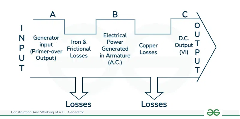
Power Flow Diagram
Referring to the power flow diagram,
Iron and friction losses = A – B.
Copper Losses = B-C
As a result, the efficiency of a DC generator may be determined for all three stages:
Mechanical efficiency
To calculate mechanical efficiency, use the formula:
ηmech = B / A = Power developed in armature (Eg Ia) / Mechanical power input (Pi)
Electrical Efficiency
To calculate electrical efficiency, use the formula
ηelect = C/B = Electric Power Output (VIL)/Power Developed in Armature (Eg Ia)
Applications of DC generators
There are several types of DC generators available for a variety of applications. The applications of these DC generators depending on their properties are discussed below:
Applications for Separately Excited DC Generators
- Because of their ability to provide a broad range of voltage output, they are commonly employed in laboratories for testing.
- Separately excited generators maintain a constant output regardless of field excitation. Because of this quality, they are used as a power source for DC engines, whose rates must be adjusted for various purposes. Ward Leonard’s speed control systems is a example.
Applications for Shunt DC Generators
- They are used to provide general illumination.
- They are used to charge batteries since they may be configured to provide a consistent output voltage.
- They are used to provide stimulation to alternators.
- They are also utilized as miniature power supplies.
Applications for Series DC Generators
- They are used to provide field excitation current in DC trains for regenerative breaking.
- These generators are employed as boosters to compensate for voltage drops in feeders in a variety of distribution systems, including train service.
- These generators are most commonly employed in series arc lighting.
Applications for Compound DC Generators
- Cumulative compound generators are used for illumination, power supply, and heavy power service due to their constant voltage properties. They are primarily overly compounded.
- Total compound generators are also used to power a motor.
- Level compound generators are commonly used for small-distance operations, such as power supply for hotels, workplaces, houses, and lodges.
- Because of its strong demagnetization armature response, differential compound generators are employed in arc welding applications requiring a big voltage drop and steady current.
Advantages of DC Generators
- Simple in build and design.
- They are used to run huge machinery.
- These generators may provide power to huge motors.
- Heavy electric gadgets are powered by employing DC generators.
- A DC generator basically reduces electric fluctuations in the armature and provides a constant supply.
Disadvantages of DC Generators
- A significant disadvantage of a DC generator is that it cannot be utilized with a transformer.
- DC generators have low efficiency.
- The current flowing in the generator undergoes numerous losses such as Eddy current losses, copper losses, mechanical losses, among others.
- DC generators installed over a long distance may face significant voltage dips.
Conclusion
A DC generator is a mechanical device that transforms a mechanical input to an electrical output, and it is used to generate electricity. The DC generator has several applications in daily life, including powering appliances and operating heavy machinery in industries. The DC generator’s operating concept is based on Faraday’s law. DC generators provide various advantages, including lower output fluctuations and suitability for large machinery. However, DC generators have a few drawbacks: they cannot be utilized with transformers and may experience voltage dips.
FAQs on Construction And Working of a DC Generator
What is a DC generator?
A DC generator is a machine that converts mechanical energy into direct current (DC) electrical energy. It operates on the principle of electromagnetic induction, generating a voltage when a conductor moves inside an magnetic field.
Where are DC generators used?
DC generators were generally used in different applications, including early electrical power age and as a power hotspot for battery charging. however, they have generally been replaced by more efficient and flexible devices like alternators and rectifiers.
How does a DC generator work?
DC generators work in view of Faraday’s law of electromagnetic induction. At the point when a guide moves in an attractive field, an electromotive power (EMF) is prompted. In a DC generator, this EMF is then changed over into an direct current using a commutator.
What are the types of DC generators?
There are two main types of DC generators: series-wound and shunt-wound. Series-wound generators have the field winding connected in series with the armature, while shunt-wound generators have the field winding connected in parallel with the armature.
What is the role of a commutator in a DC generator?
The commutator in a DC generator is a rotating switch that switches the ongoing course in the coil windings. It ensures that the generated current flows in a one direction in the external circuit, making a constant and unidirectional flow of electricity.
Share your thoughts in the comments
Please Login to comment...