Radar, an abbreviation for Radio Detection and Ranging, is a critical innovation in the field of electrical engineering. Initially produced for military purposes, radar systems have tracked down broad applications in different domains, including meteorology, flight, and navigation. This article gives an inside-and-out investigation of radar systems, focusing on their essential standards, terminology, block diagrams, working systems, and applications. This sends out radio waves to detect objects through radio waves in order to find the speed and position of the object.
Definition of Pulse Radar
A Radar system that operates with a pulse signal, and aims for detecting stationary targets is called Pulse Radar.
What is a Radar?
RADAR is a truncation for Radio Detection And Ranging. A system utilized for detecting and locating the presence of objects like boats, vehicles, airplanes, and so on. by transmitting electromagnetic signals in space is known as the Radar system.
Fundamentally, radar is utilized to gather the data connected with the object or target like its range and area by transmitting electromagnetic energy and inspecting the echo received from the distant object.
History of Radar
Before World War II, radar was developed for military purposes to secretly detect the presence of unknown objects. At first, the transmitting tubes were not that strong and subsequently worked at an exceptionally low frequency of around 60 MHz
Yet, further improvement in the field and utilization of magnetrons has stretched out the frequency reach to a higher level.
As indicated by the activity performed by the radar, it is vital to have a framework that can precisely distinguish the presence of the objective. So for this reason, narrow beam antennas with short-frequency are utilized that compare to upper UHF and microwave frequencies. In this way the US armed developed created microwave radar system and such a framework can decide the place of the item to inside 0.1° and 25 meters.
Important Terminologies of Radar Systems
Understanding the key Terminology related with radar systems is fundamental for getting a handle on the standards and usefulness of these refined innovations. Here, we discuss further into the essential terms used in radar systems:
- Transmitter: The transmitter is a crucial part that produces and emanates radio recurrence (RF) beats. These heartbeats travel through space and structure the premise of the radar signal conveyed to distinguish objects.
- Receiver: The beneficiary is answerable for catching and handling the signs that are reflected back to the radar framework in the wake of connecting with targets. It assumes an essential part in removing data about the distinguished items.
- Antenna: The receiving wire fills in as the connection point between the radar framework and the encompassing space. It coordinates the sent heartbeats towards the objective and gathers the reflected signs for additional handling. Design options for antennas include parabolic, phased array, and horn designs.
- Target: In radar wording, the expression “target” alludes to the item or element that the radar framework is intended to distinguish, find, and track. Targets can incorporate airplane, ships, vehicles, climate peculiarities, or different objects of interest.
- Radar Cross Section (RCS):Radar Cross Segment is a proportion of the objective’s capacity to reflect radar signals. It evaluates the objective’s reflectivity or the region it presents to the radar framework. Focuses with bigger RCS values are by and large simpler to distinguish.
- Doppler Effect: The Doppler effect is a peculiarity in radar frameworks brought about by the movement of an objective. It brings about a recurrence shift in the reflected signs, permitting the radar framework to decide the objective’s outspread speed.
- Modulator: The modulator controls the span or width of the RF beats created by the beat generator. This control is essential for changing the radar framework’s heartbeat attributes, influencing boundaries like reach goal and most extreme unambiguous reach.
- Polarization: Radar waves can be captivated in various directions. Polarization is a property of the electromagnetic waves, and the decision of polarization can affect the radar’s exhibition in different circumstances, like lessening the effect of precipitation in climate radar applications.
- Display: The presentation unit presents the data got from the gotten radar signals in a fathomable configuration. Showcases can go from conventional screens showing blips on a radar degree to cutting edge graphical UIs in present day radar frameworks.
- Range: The term “range” refers to the distance between the target and the radar system. Radar frameworks measure range by working out the time it takes for a communicated heartbeat to make a trip to the objective and back, taking into account the speed of light.
- Pulse Generator: The beat generator is liable for making short explodes or beats of radio recurrence energy. These heartbeats are communicated into space and act as the reason for estimating the reach and speed of targets.
- Range: The distance between the radar and the target is referred to as the “range” of the target. We are aware that the radar sends a signal to the target, which then sends back an echo signal to the radar at the speed of light (c). Let “T” represent the time it takes for the signal to travel from the radar to the target and back. Since the distance between both of the radar and the objective is R, the two-way distance between them will be 2R.
The Speed formula is now as follows.
Speed = Distance/Time
Distance = Speed * Time
2R = C * T
R = CT/2 …….. (1)
Pulse Repetition Frequency: Each clock pulse should be utilized to communicate a radar signal. In order echo signal related with the current clock pulse to be received before the following clock pulse, it is urgent to appropriately choose the delay between the two clock beats. The normal type of a radar wave is displayed in the going with figure.
As depicted in the figure, the radar sends out a signal on a regular basis. It has several short pulses that are rectangular in shape. The time between clock pulses is referred to as the pulse repetition time.
The proportional of pulse repetition time is pulse redundancy frequency, or fP.
fP = 1/TP …….. (2)
In this manner, the pulse repetition frequency is only the frequency at which the signal from a radar is sent.
Maximum Unambiguous Range: We know that each clock pulse should to bring about the transmission of a radar signal. The echo signal corresponding to the current clock pulse will be received after the subsequent clock pulse if we select a shorter time interval between the two. The objective’s reach gives off an impression of being more limited than it really is thus.
To ensure that the echo signal comparing to the current clock pulse is received before the beginning of the following clock pulse, we should pick the delay between the two clock pulses. This is trailed by a presentation of the objective’s real reach, normally known as the target’s maximum unambiguous range or essentially maximum unambiguous range.
Replace R = R un and T = TP in equation 1
Run = CTP / 2 …….. (3)
The pulse time, TP, is obtained from equation 2 as the proportional of the pulse repetition frequency, fP. In math, it has the following representation:
TP = 1 / fP………(4)
Replace Equation 4 in Equation 3
Run = C(1/fp) / 2
Run = C/2fp ……..(5)
Equation 3 or Equation 5 can be used to determine the target’s maximum unambiguous range.
By changing the values of C and TP in Equation 3, we might acquire the worth of the target’s maximum unambiguous range, Run.
By replacing the value of C and fP in Equation 5, we can get the worth of the target’s maximum unambiguous range, Run
Maximum Range: At the point when we consider what amount of time it requires for the echo signal to show up to the radar after the signal is communicated from the radar as pulse width, we will get the target’s base range. It is otherwise called the target’s most brief range.
Replacing R = R min and T = τ in equation 1
Rmin = Cτ/2 …….. (6)
By changing the values of C and τ in equation 6, we can acquire the value of the target’s minimum range, or Rmin.
Block Diagram of Pulse Radar
Pulse Radar uses single antenna for both transmitting and receiving of signals of Duplexer. Notwithstanding the various benefits, radar systems in all actuality do introduce difficulties, for example, helplessness to electronic countermeasures, high execution expenses, and potential protection concerns. Finding some kind of harmony between utilizing the advantages of radar innovation and tending to these difficulties stays a focal point of progressing innovative work.
As innovation keeps on propelling, radar systems are probably going to assume an undeniably essential part in tending to arising difficulties and open doors. Radar systems continue to demonstrate their adaptability and necessity in our interconnected world, whether it’s for monitoring the skies, maritime safety, disaster response, or scientific research.
The continuous quest for development in radar innovation guarantees further enhancements, pushing the limits of what is feasible and reaffirming radar’s status as a foundation of current designing and logical accomplishment. Following is the block diagram of Pulse Radar:
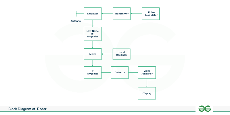
Block Diagram of Pulse Radar
- Pulse Modulator: A pulse modulator is utilized to construct synchronization between the waveform generator and transmitter. The pulse modulator causes the turning on and off of the power amplifier as per the input pulses produced by the waveform generator.
- Transmitter: The waveform generator sends the signal to the transmitter. A magnetron, traveling wave tube, or transistor amplifier could make up the transmitter section. On account of pulse radar, magnetrons are generally utilized as transmitters yet at whatever point there exists a requirement for high normal power then amplifiers are utilized.
- Duplexer: It is a microwave switch, which interfaces the Radio wire to both transmitter segment and beneficiary segment on the other hand. Receiving wire sends the beat balanced signal, when the duplexer associates the Antenna to the transmitter. Additionally, the sign, which is gotten by Receiving antenna will be given to Low Commotion RF Speaker, when the duplexer associates the Antenna to Low Noise RF Amplifier.
- Low Noise RF Amplifier: The receiver should be superheterodyne. The unit goes about as the input stage for the receiver area. An RF pulse is produced by the RF amplifier in proportion to the transmitted signal’s echo. A radar system operates such that it emanates electromagnetic energy into space and distinguishes different perspectives connected with objects by breaking down the reverberation produced when the transmitted energy gets re-transmitted by the object. The electromagnetic signal is produced by the transmitter unit and is radiated in space by the radar antenna. While the receiver performs extraction of data from the sign got by the radar antenna.
- Local Oscillator: It delivers a sign having stable recurrence. The result of Neighborhood Oscillator is associated with Blender. We know that when a system transmits an electromagnetic wave, it reflects or reradiates some of its components when the medium’s conductivity medium. This variety in conductivity emerges because of the presence of an article either fixed or moving. Subsequently delivering a echo.
- Mixer: We realize that Blender can create both aggregate and distinction of the frequencies that are applied to it. Among these, there will be an intermediate frequency (IF) difference in the frequencies.
- IF Amplifier: Assuming speaker enhances the Transitional Recurrence (IF) signal. Only the Intermediate Frequency, which is obtained from the Mixer and amplified by the IF amplifier depicted in the figure, is permitted. It works on the Sign to Clamor Proportion at yield.
- Detector: It demodulates the signal, which is gotten at the result of the IF amplifier. The radar system receives the echo by the help of an antenna in order to analyze it and have to get location of the object. The distance between the target and the radar system is known as the range.
- Video Amplifier: This device, as its name suggests, amplifies the video signal that comes from the detector’s output. The reach to a still up in the air by the estimation of the time taken by the transmitted signal to arrive at the item and return to the radar. What’s more, the area of the fixed item in the still up in the air from the point pointed by the radio wire when the reverberation got is of maximum amplitude.
- Display: It shows the enhanced video signal on CRT screen. For a moving object due to the Doppler effect, there exists a change in the frequency of the re-radiated signal. Additionally, the frequency shift is proportional to the object’s radial velocity.
Working and Construction of Radar System
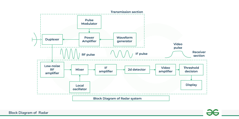
Working and Construction of Radar System
The components and its working is shown below:
Transmitter Section
The transmitter section is made out of the following units:
Waveform Generator: The waveform generator (normally a magnetron) produces a radar signal at low power which is to be communicated into space.
Transmitter: The signal generator sends the signal to the transmitter. A magnetron, traveling wave tube, or transistor amplifier could make up the transmitter section. In the case of radar, magnetrons are generally utilized as transmitters yet at whatever point there exists a requirement for high average power then amplifiers are used.
Pulse modulator: A pulse modulator is utilized to construct synchronization between the waveform generator and transmitter. The pulse modulator causes the turning on and off of the power amplifier as per the input pulses produced by the waveform generator.
Duplexer: A duplexer is fundamentally used to form isolation among transmitter and receiver section. A duplexer permits the utilization of a single antenna for both transmission and receiving purpose. However, both the segments work at various power level, in this manner, a duplexer is utilized to separate the two segment.
Accordingly the signal from the transmitter is given to the antenna through the duplexer. As the duplexer short-circuits the input of the receiver section.
Receiver Section
The accompanying parts are available inside the receiver section
RF amplifier with low noise: The recipient should be superheterodyne. The unit goes about as the info stage for the collector area. An RF pulse is produced by the RF amplifier in proportion to the transmitted signal’s echo.
Mixer and Local Oscillator
- An IF pulse is created from the RF pulse that is received by the low noise RF amplifier. Generally, the RF enhancer acts at the info phase of the collector area yet some of the time the mixer acts at the information stage by killing the RF intensifier.
- However, this prompts a less delicate getting segment because of the great commotion figure of the blender.
IF amplifier: The Assuming that heartbeat created by the blender circuit is intensified by the IF enhancer. It improves the received signal’s SNR by acting as a matched filter. By reducing the effects of unwanted signals, it also improves the receiver section’s ability to detect echoes. The recipient’s transfer speed is related with the data transmission of the IF stage.
Second Detector or Demodulator: This unit is only a precious stone diode that performs demodulation of the sign by isolating the sent sign from the transporter.
Amplifier for video: This unit enhances the got sign to a level that can be shown on the screen.
Video Amplifier
- This unit comes to the conclusion about the presence of the objective in space. In essence, it has a threshold limit that is compared to the received signal’s magnitude.
- The output signal indicates the target’s presence if it exceeds the threshold value. In any case, it is accepted that main the commotion part is available in the space.
Display
- The receiver section’s final output is displayed on the display unit. PPI i.e., plan position sign is ordinarily utilized as the radar show unit.
- It presents the reach and area of the article by planning it in polar directions. CRT is used to implement PPI.
The result signal adjusts the electron light emission cathode beam tube to allow the electron pillar to clear from the Middle in the outward course of the cylinder. Additionally, this sweep demonstrates rotation in sync with the antenna’s pointing.
The distance between the target and the radar is known as the range of the target, or essentially range. The complete distance between the radar and target on a two-way communication line will be 2R on the grounds that the objective communicates a reverberation sign to the radar and the radar responds by conveying a message to the objective.
The quantity of frequencies N that are available in a two-manner correspondence line between the Radar and target will rise to 2R/λ. assuming it is one frequency.
We know that one frequency rises to a two-radian angular excursion. Subsequently, 4πR//λ radians will be equivalent to the whole point of outing created by the electromagnetic wave all through the two-way correspondence channel between the radar and target.
The angular frequency ω mathematical equation is as per the following:
w= 2πf…….(1)
The accompanying condition represents the mathematical association between the phase point ϕ and angular frequency w .
w= dϕ/dt……(2)
Since the left-hand side terms of equations 1 and 2 are identical, look at their right-hand side terms.
2πf= dϕ/dt
f= 1/2π dϕ/dt……..(3)
Substitute, f = fd and ϕ = 4πR/λ
fd=1/2π d/dt (4πR/λ)
fd=1/2π 4π/λ dR/dt
fd= 2Vr/λ …….(4)
Where,
The Doppler frequency is fd.
The general speed is Vr.
The Doppler frequency fd can be obtained by changing the values of Vr in Equation 4.
Replace λ =C/f in Equation 4.
fd = 2Vr/C/f
fd = 2Vrf/C……..(5)
Where,
f is the sign’s transmission frequency
The speed of light is equivalent to 3* 108 m/s, or C.
By changing the values of Vr, f, and C in equation 5, we might determine the value of the Doppler frequency, fd
Advantages of Radar System
- Long-Range Detection: Radar systems succeed at long-range recognition, taking into consideration early identification of targets, whether they are airplane, ships, or different objects of interest.
- All-Weather Operation: Dissimilar to a few optical systems, radar is equipped for working in different weather patterns, including rain, fog, and darkness. This makes it especially significant for military reconnaissance and air traffic control.
- Reduced Dependency on Light Conditions: Dissimilar to optical systems that depend on visible light, radar works utilizing radio waves, making it powerful even in low-light or complete darkness situations.
- Measurement of Speed: Radar systems can quantify the speed of moving targets in view of the Doppler shift in the recurrence of reflected signals. This component is pivotal for applications like traffic authorization and weather conditions following.
- Tracking a Target: Multiple targets can be tracked simultaneously by radar systems, providing useful information about their velocities and trajectories.
- Adaptable Applications: Radar systems have different applications, going from military defense and reconnaissance to regular citizen applications, for example, air traffic control, weather conditions checking, and ground-based observation.
- Constant Monitoring: A persistent surveillance capability that is essential for security and safety is provided by radar systems, which can monitor a designated area continuously and in real time.
Disadvantages of Radar System
- Maintenance and Implementation cost is high: Planning, conveying, and keeping up with radar systems can be costly. The expense incorporates the establishment of radar hardware, continuous support, and occasional moves up to stay aware of innovative progressions.
- Complexity of processing data: Handling the huge measure of information created by radar systems, particularly in present day staged exhibit radar, can be complex and may require modern calculations and registering assets.
- Interference in Crowded Electromagnetic Conditions: In conditions with various electronic gadgets and signals, radar systems might encounter obstruction, possibly prompting diminished precision or false readings.
- Potential for Signal Absorption by rain: In specific atmospheric conditions, for example, weighty downpour, radar signals can be retained, prompting decreased location reach and precision in climate radar applications.
- Privacy Concerns: In regular citizen applications, the utilization of radar for reconnaissance raises security concerns. Finding some kind of harmony between security necessities and individual protection is a test in certain specific situations.
- Altitude Resolution is limited :Radar systems might have limits in precisely deciding the height of an objective, particularly while managing objects at comparable reaches.
- Vulnerability to Electronic Countermeasures: Radar systems can be helpless to electronic countermeasures like sticking and satirizing, which can think twice about adequacy in specific circumstances.
Applications of Radar System
- Military Surveillance: Radar is widely utilized in military tasks for observation, target location, following, and early admonition frameworks. Ground-based, airborne, and maritime radar frameworks add to situational mindfulness and safeguard.
- Ground-Based Monitoring: Radar systems are utilized for ground-based reconnaissance in line control, basic foundation assurance, and edge security. They can identify and follow unapproved interruptions or exercises in got regions.
- Air Traffic Control (ATC): Radar is a foundation of aviation authority systems, empowering regulators to screen the position, elevation, and speed of airplane. Essential and auxiliary radar systems aid protected and proficient air traffic the board.
- Weather conditions Observing and Determining: Climate radar systems are utilized to screen precipitation, recognize extreme climate peculiarities, and give significant information to weather conditions gauging. Doppler radar investigates wind designs and recognize the power of tempests.
- Aeronautics Weather conditions Checking: Radar systems at air terminals assist with checking weather patterns, particularly during departure and landing. This data is basic for guaranteeing safe flight activities and limiting the effect of antagonistic climate on aeronautics
- Navigation and Impact Aversion: Radar systems on boats and airplane work with route by distinguishing close by vessels or airplane, assessing their positions, and supporting crash evasion. Increasing aviation and maritime safety requires this.
- Search and Rescue Operations: Radar helps search and salvage endeavors by finding trouble signals from boats, airplane, or people in crisis circumstances. It gives a fast and viable method for distinguishing the area of possible survivors.
- Space Surveillance: Radar systems add to space reconnaissance by following and observing the directions of articles in Earth’s circle. This is fundamental for impact evasion and space trash the executives.
- Traffic Control and Enforcement: Radar innovation is utilized by policing speed requirement on streets. Traffic signal radar helps screen vehicle speeds, uphold traffic guidelines, and upgrade street security.
- Wildlife life Monitoring: Radar is used in natural life observing and preservation endeavors. It helps track the development of birds and different creatures, giving important information to investigate and alleviating expected clashes with human exercises.
Conclusion
In conclusion, radar systems stand as fundamental parts of present day mechanical scenes, offering a bunch of utilizations that range across military, flying, meteorology, and different fields. The capacity to emanate, get, and decipher radio recurrence signals has reformed the manner in which we identify, track, and figure out our environmental elements. The benefits of radar, including long-range location, all-climate activity, and flexible applications, highlight its significance in both regular citizen and protection areas. Radar’s part in improving security and effectiveness in air travel through aviation authority, checking atmospheric conditions for exact gauging, and adding to military guard and observation couldn’t possibly be more significant. The steady development of radar innovation, from customary heartbeat radar frameworks to further developed staged cluster and manufactured gap radar, mirrors a continuous obligation to further developing exactness, responsiveness, and unwavering quality.
FAQs on Radar Systems
How does radar technology work?
Emitting radio frequency signals that bounce off objects and return as echoes is how radar technology works. By breaking down the time deferral and Doppler shift of these reverberations, radar frameworks can decide the distance, speed, and different qualities of the identified articles.
How does radar contribute to security and defense?
Radar systems are significant for public safety, giving early admonition capacities against likely dangers, including approaching rockets or airplane. They add to air guard, observation of boundaries and shores, and checking exercises in essential areas. Additionally, missile defense systems are dependent on radar.
Are there security concerns related with radar innovation?
The monitoring capabilities of radar can raise privacy concerns in civil applications like ground-based surveillance and traffic control. Finding some kind of harmony between the advantages of radar in guaranteeing wellbeing and security and tending to protection contemplations is a continuous test.
What are a few future in radar innovation?
The integration of artificial intelligence for improved signal processing and target recognition, the exploration of radar applications in emerging fields like autonomous vehicles, and phased-array radar for improved adaptability are all future trends in radar technology.
Can radar systems operate in adverse weather conditions?
Indeed, one of the upsides of radar is its capacity to work in different atmospheric conditions, including precipitation, haze, and murkiness. Climate radar frameworks, specifically, are intended to screen precipitation and serious climate peculiarities.
Share your thoughts in the comments
Please Login to comment...