In this article, we will be discussing about attenuation. We will also discuss about attenuation in optical fiber and networking. We will look into the various factors that causes attenuation in optical fiber and networking. We will discuss about attenuation coefficient. We also will discuss how can we measure attenuation and the methods that are available to measure. In addition to this, we will discuss how can attenuation be prevented. We will also compare attenuation with amplification and see their differences. Later in this article, we will discuss about the various advantages, disadvantages and application of attenuation.
What is Attenuation?
Attenuation is a term in communication that refers to loss (reduction) in signal strength when a signal is transmitted from sender to the receiver. This loss happens due to a variety of factors. Attenuation can happen in both analog and digital signal. It is measured using decibels(dB).
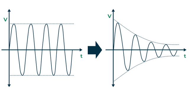
Attenuation in a Signal
Attenuation in Optical Fiber
Optical fibers are used to transmit signals using light over large distances. Attenuation in optical fibers occurs when the light intensity is reduced as it propagates through the fiber. It is a type of optical loss and it limits the distance over which it can travel.
Types of Attenuation in Optical Fiber
There are two types of attenuation in optical fiber,
- Intrinsic Attenuation
- Extrinsic Attenuation
Intrinsic Attenuation
Intrinsic attenuation happens due to absorption and scattering.
- Absorption – It happens due to the imperfections in the optical fiber. It is caused by the atomic defects in the glass components. When light passes through fiber it may be absorbed by one or more components of glass. Absorption loss can happen from transition metal element impurities. This loss value is generally 0.4 dB/km at 1310nm and 0.25 dB/km at 1550nm.
- Scattering – It happens due to fiber materials and structural imperfections. Fiber structures have regions of high and low molecular density. Also several oxides present in glass leads to compositional fluctuations. This scattering of lights lead to loss of power or attenuation. Rayleigh scattering arises from variation in the density of fiber materials leading to random fluctuations.
Extrinsic Attenuation
Extrinsic attenuation is the loss that is caused by external factors. It happens from Radiative loss(bending loss) and coupling loss(splicing and connector loss).
Radioactive Losses
It occurs when a fiber undergoes a bend. Fiber bends are of two types macro bends and micro bends.
- Macro bending loss happens if the radius of the core is larger than the fiber diameter then it may cause large curvature at the positions where the fiber is bend and light will escape.
- Micro bending loss happens due repetitive small scale fluctuations caused by non-uniformities inside the fiber which appears due to non uniform pressure during cabling or during manufacturing.
-660.png)
Bending Losses
Coupling Losses
- Fiber optic splicing also causes losses. By joining two optical fibers end to end splicing aims to ensure that the light passing through it is almost as strong as the original wire without any joins. Splicing loss value is generally 0.05dB to 0.3dB.
- Connector losses or insertion losses in optical fiber results from the insertion of a device in a transmission line or optical fiber. This loss is generally around 0.3dB to 0.75dB.
-660.png)
Losses in Optical Fiber
Measurement of Attenuation in Optical Fiber and Attenuation Coefficient
The attenuation coefficient is an important parameter of optical fiber which is used to measure the rate at which the intensity of light decreases. It is denoted by [Tex]\alpha
[/Tex](alpha).
The attenuation coefficient () is mathematically represented as:
Number of decibels = 10 log10(Pi/Po)
Power P(L) at a distance L is given as ,
P(L)=P(0)e–[Tex]\alpha
[/Tex]L
Where P(0) is power at origin
Then attenuation coefficient of fiber in decibel per kilometer is,
[Tex]\alpha
[/Tex] = (10/L) log(P(0)/P(L))
where,
- [Tex]\alpha
[/Tex] is the attenuation coefficient (in dB/km)
- L is the length of the fiber over which the measurement is taken
- P(0) is the initial optical power
- P(L) is the optical power at distance L from input
Higher the attenuation coefficient higher is the loss while lower value means lower loss and a high quality fiber.
Methods used in measuring Attenuation
Some of the general methods used in measuring the attenuation are as follows:
- OTDR Method
- Total Fiber Attenuation
- Power ratio method
- Voltage Ratio Method
- Audio Frequency (AF) Substitution Method
- Intermediate Frequency (IF) Substitution Method
- Radio Frequency (RF) Substitution Method
OTDR(Optical Time Domain Reflectometer)
It is the most common instrument for the measurement of loss. It is essentially an optical radar. The laser source launches a narrow pulse of light inside the optical fiber and measures its reflection.
As the pulse travels inside the fiber it gets Rayleigh scattered. The backward scattered light is collected by the photodetector and displayed as a function of time. The pulse and the back scattered both get attenuated as they travel. The intensity of the back scattered light will be then twice the loss of the fiber. The location on the fiber can be found from the delay of the back scattered light. Since the Rayleigh scattering is very weak in the optical fiber, the back scattered light intensity is very small to be detected in the presence of electrical noise. Therefore, multiple pulses are transmitted and the received signal is integrated to improve the signal to noise ratio of the OTDR trace. Delay between the pulses has to be more than the round trip delay on the fiber.
The OTDR can also be used to monitor the status of the optical fiber while in operation. It can detect faults like tempering of the fiber as well as breakage in the fiber.
-660.png)
OTDR Block Diagram
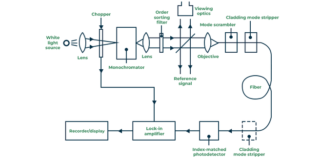
Total Fiber Attenuation
Cut-back or differential method is the commonly used technique for determining the attenuation per unit length. A white light source is mechanically chopped at a low-frequency of a few hundred hertz. This allows the lock-in amplifier at the receiver to perform phase-sensitive detection. The chopped light is then passed through the monochromator which uses a prism to select the required wavelength at which the attenuation has to be measured. By using a microscope objective lens the light is filtered before focusing onto the fiber. A beam splitter is used to provide light for viewing optics and reference signals are used for compensating output power fluctuations. The fiber is put through a cladding mode stripper to remove light launched into the fiber cladding.
A mode stripper is used at the fiber end to remove any power which is scattered from the core to the cladding. The power at the end in detected using avalanche photodiode. At last the electric output from the photodiode is fed to a lock-in amplifier whose output is recorded.
The attenuation from this method can be found from the following mathematical equation,
[Tex]\alpha
[/Tex] = 10/(L1-L2)log10(P02/P01)
where,
- L1 is the original fiber length
- L2 is the cut-back fiber length
- P01 output optical power at a specific wavelength from original fiber length
- P02 output optical power at a specific wavelength from cut-back fiber length
[Tex]\alpha
[/Tex] = 10/(L1-L2)log10(V2/V1)
where,
- V1 is the output voltage from original fiber length
- V2 is the output voltage from cut-back fiber length
Cut-Back Block Diagram
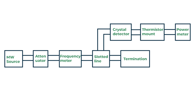
Power Ratio Method
The first step in this method is to measure the input and output power of the microwave bench without the device is calculated. In the second step the input and output power of the microwave bench along with the device is calculated. The drawback of this method is that if the input power is low and attenuation is large then measurement may not be accurate.
Power Ratio Set up-1

Power Ratio Set up-2
Radio Frequency Substitution Method
In this method, the output power of the microwave bench is measured with the network whose attenuation has to be calculated. Again the output power is calculated by replacing the network with a precision calibrated attenuator. The attenuator is then adjusted to obtain the same power as the network. This method avoids the drawback of the power ratio method.

RF Substitution set up-1

RF Substitution set up-2
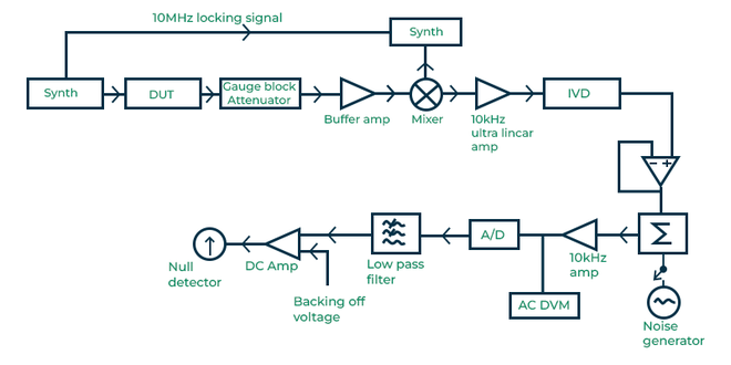
Voltage Ratio Method
In this method, a digital Voltmeter is used to measure the potential difference across a feed-through terminator, firstly directly connected to the matching attenuator and then the device is inserted and the difference is measured.
-660.png)
Voltage Ratio Setup
Audio Frequency Substitution Method
In AF substitution method, the attenuation of the device is measured by comparison with an audio frequency standard. The output voltage is measured first without the device under test from the signal generator. Then the device is connected and the output voltage is measured. The signal generator is set to the desired test frequency and the ratio of the voltages in two cases gives the attenuation at that frequency
AF Substitution Method
Intermediate Frequency Substitution Method
In this method, comparison is done with an IF attenuation standard like IF piston attenuator. In parallel IF substitution system, a reference signal is compared with the IF input signal. A turn phase sensitive detector is used is used to detect and display the difference between both the signals. When the device under test is inserted the system is brought to a null using the piston attenuator and the difference in two settings is used to find the attenuation.

IF Substitution Method
Attenuation in Networking
Attenuation in networking is the loss of signal strength as the signal is transmitted from the sender to receiver. This happens in both wired and wireless communication. This impacts the quality, range and reliability of the data that is being transmitted.
Causes of Attenuation in Networking
- Distance – Distance between the sender and receiver contributes to attenuation. The more the distance the more interference and noise it will experience on its way from source to destination. An example of this can be the strength of mobile signal reduces as you move away from the cell tower.
- Frequency and Noise – Whenever a signal is transmitted it will encounter some noise and when noise is encountered it will affect the signal strength and thus attenuate the signal. This noise is generated from the electromagnetic field caused by cables, electronic devices that are near the signal. High frequency signals experiences more attenuation because they have shorter wavelength and thus will experience more absorption.
- Medium – The medium through which the signal travels also causes attenuation because of the characteristics of the medium. For example copper cables have more attenuation than optical fiber.
- Interferences – The interferences from external sources like buildings, glass panes and other obstacles can block, reflect or absorb the signal causing signal loss. Also electromagnetic interference is responsible for attenuation.
Measurement of Attenuation in Networking
Attenuation in networking is measured in decibels(dB) and we can calculate it using the formula:
Attenuation(in dB) = 10*log10(Ps/Pd)
Where,
- Ps is the signal power at source
- Pd is signal power at destination
Attenuation can also be expressed in terms of voltage
Voltage Attenuation(in dB) = 20log10(Vs/Vd)
Where,
- Vs is the voltage of signal at source
- Vd is the voltage of signal at destination
How Attenuation can be Prevented?
- The most common way to prevent attenuation is used of repeaters which will regenerate the signal if the signal received is weak hence reducing attenuation.
- The cables should be checked during manufacturing and installations to prevent bending and imperfections so that losses can be minimized.
- Another way of reducing attenuation is amplification. Amplification is more effective than repeaters because it only increases the amplitude or strength of signal when the received signal is weak.
- Use of high quality fiber optics with better design to have low attenuation coefficient and reduce intrinsic losses.
- Use of error correcting codes so as to maintain data reliability
- Communication should be done over a particular frequency so as to reduce electromagnetic interference.
When we prevent attenuation we have certain advantages. The first advantage is that less power is consumed as power can be saved when signal is transmitted with out any obstacle thus reducing operational costs. Also it will provide higher data integrity and reliability as chances of wrong data transmission will be reduced.
Attenuation Vs Amplification
Attenuation | Amplification |
|---|
It is the reduction in signal strength as it propagates from source to destination.
| It is the method to increase the signal strength to compensate the loss of signal.
|
It is a passive process which occurs naturally due to intrinsic and extrinsic factors.
| It is a active process which occurs through the use of amplification devices.
|
It causes signal degradation, data loss and limits range.
| It results in enhanced signal quality, data reliability and improved range by overcoming attenuation.
|
It happens because of interference, scattering, absorption, bending losses.
| It is done using signal boosters, amplifiers, repeaters.
|

Attenuation vs Amplification
How to Increase Signal Strength to Prevent Attenuation
Amplification techniques are Used to increase signal strength to prevent attenuation.Signal amplification is an electrical method of increasing the strength of line signals through various Technical processes. In addition to strengthening the signal through amplification, the network also incorporates noise cancellation logic to prevent possible corruption of the underlying message data. One common method of signal amplification is the integration of a signal amplifier into the circuitry of a network repeater device. This repeater serves as an intermediary between two message endpoints, performing the following tasks:
- Reception: The repeater receives data from the original sender or another upstream repeater.
- Amplification: The received data is processed through the amplifier, electrically increasing its strength.
- Transmission: The repeater then transmits the strengthened signal forward to its ultimate destination.
In addition to repeaters, it is also effective to use directional antennas and other antenna upgrades to boost signal. These improvements can play an important role in addressing attenuation issues in communication networks and maintaining signal integrity.
Advantages of Attenuation
- It can used for control of signal strength, in applications where strong signal need to be attenuated for proper operation.
- It can used for noise reduction. Unwanted noise can be removed using attenuation for better quality signal transmission.
Disadvantages of Attenuation
- The biggest disadvantage of attenuation is loss of signal as this leads to poor signal quality and loss of data.
- Attenuation leads to reduction in distance over which signal can be transmitted. This posses as a challenge for long range communication
- Increase in operational cost as additional equipment like amplifiers, repeaters or signal boosters are required to compensate the signal loss.
Applications of Attenuation
- It can used for volume control in electronic equipment and in broadcasting stations.
- In optical fiber attenuation is required to obtain proper match of power level between transmitter and receiver and that the signal strength remains constant over long ranges.
- In RF, attenuators are used for protective dissipation of power in measurement of RF signals.
- It is used for obtaining low voltages in experiments conducted in laboratories.
- In digital and analog circuits where high voltage can damage the circuit attenuators are used to prevent high voltage.
- Fixed attenuators are used to enhance impedance matching within the circuits.
Conclusion
In conclusion, attenuation is a natural aspect of communication that leads to loss of signal strength as the signal propagates from source to destination. It is important that attenuation is managed properly in communication so as to obtain high quality transmission along with reliable data. It happens due to various factors like absorption, bending losses, scattering and interferences. Attenuation can be avoided using protective measures like use of amplifiers or signal boosters. As attenuation is mitigated we can ensure high quality in communication.
FAQs on Attenuation
What is the difference between attenuation and amplification?
Attenuation represents the loss of signal strength during transmission whereas amplification is the process of compensating this loss by increasing the strength of the weak signal and thus reducing attenuation.
What are some methods to reduce attenuation in wireless communication?
Methods to reduce attenuation in wireless communication are to do signal amplification using repeaters or boosters, having line of sight communication by avoiding obstacles, using proper frequency bands.
Why is attenuation a significant consideration in communication system design?
Attenuation affects the range, quality and reliability of the signal that is transmitted. Prevention of attenuation is required for reliable long-distance communication with excellent network performance.
Share your thoughts in the comments
Please Login to comment...