In some previous articles, we have seen and understood the concepts of Arduino Boards, Arduino IDEs, and the installation procedure for Arduino software. Arduino IDE (Integrated Development Environment) is an essential which makes the task of uploading code on Arduino boards, an easy task. Instead of writing them at the assembly level, the IDEs make it convenient and the codes are written in high-level languages like C and C++. Let us get introduced to the basics of Arduino Coding.
Make sure that you have an appropriate IDE for coding before starting your journey to Arduino coding. Let us study every character, command, and function that is used in Arduino. Keep your Arduino IDE switched on so that you can apply the concepts you learn from the article.
Table of Content
What is Arduino?
With the increasing demand for programming, there was a need for a device that could program electrical devices therefore, Arduino was introduced. Arduino is a board made up of several interconnected components like microcontrollers, digital pins, analog pins, power supplies, and crystal oscillators which give Arduino the ability to program electronic instruments. You must be familiar with the idea that an Arduino board can be programmed to illuminate an LED. The Arduino has its hardware and software using which it can program devices. Let us take a look at the Arduino board.
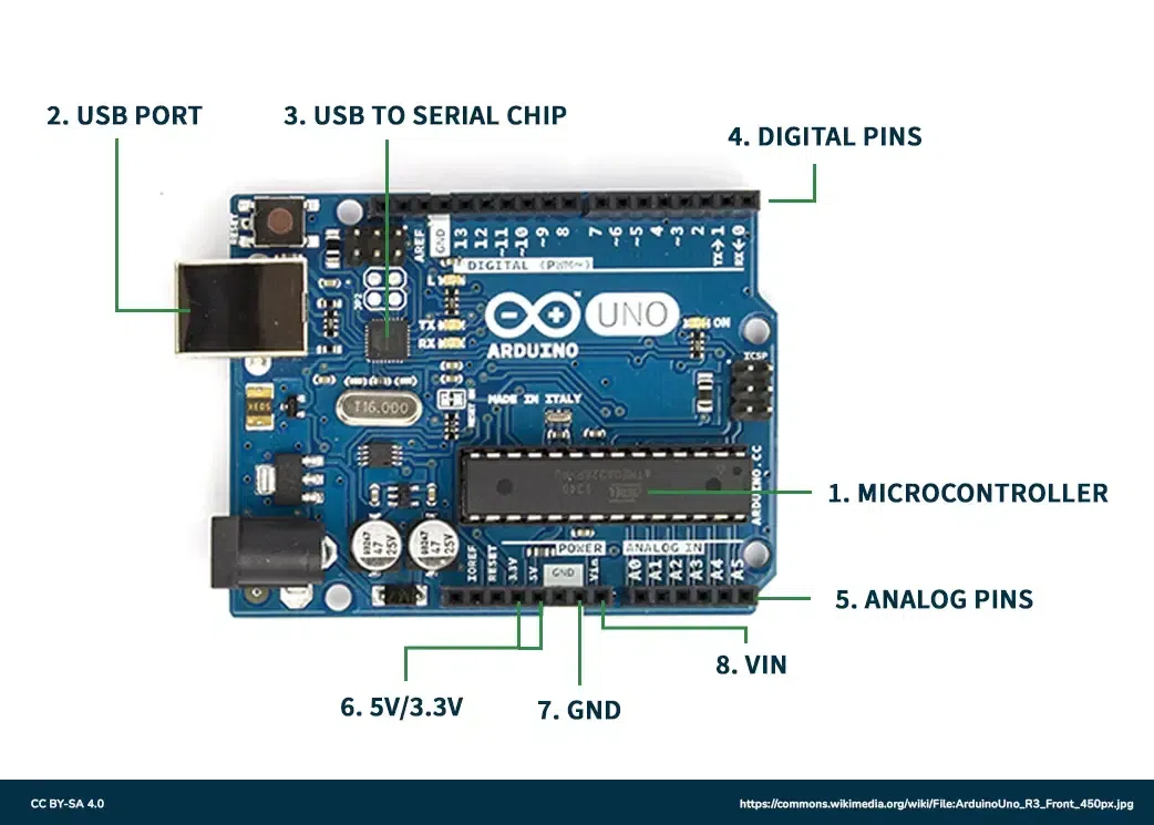
Arduino Board
- Microcontroller: The microcontroller used on the Arduino board is essentially used for controlling all major operations. The microcontroller is used to coordinate the input taken and execute the code written in a high-level language.
- Analog Reference pin: Analog pins are used for general purposes like supporting 10-bit analog-to-digital conversion (ADC) which is performed using analog the Read() function. Analog pins are particularly helpful since they can store 0-255 bits which is not possible using digital pins.
- Digital Pins: Digital pins are used for general purposes like taking input or generating output. The commands that are used for setting the modes of the pins are pinMode(), digitalRead(), and digitalWrite() commands.
- Reset Button: The reset button on the Arduino board is used for setting all the components of Arduino to their default values. In case you want to stop the Arduino in between you can use this reset button.
- Power and Ground Pins: As the name suggests, power and ground pins are used to supply the power needed for driving the Arduino board. The ground pins are usually 0V to set a reference level for the circuit.
- USB (universal serial bus): The Arduino needs certain protocols for communication purposes and the universal serial bus is used for this purpose. It helps to connect Arduino, microcontrollers with other raspberry pies.
Electronic Signals
Let us study the two types of signals that are used for communication:
Analog Signal: Analog signals can take any value in a given continuous range of values. Generally, analog signals used in Arduino are around 0V to 5V. The analog pins can take data up to 8-bit resolution therefore, they are used for taking large values as input in the Arduino. These signals carry data in a very accurate form without many errors.
Digital Signal: Digital signals can only take discrete values which are, high('1') and low('0'). These signals are usually used to Arduino on or off which requires only two values. The collection of two values (0 and 1) can be used to generate a sequence known as the binary sequence which is a collection of zeroes and ones. This is how data is transmitted without much memory requirement but this can lead to certain errors like quantization errors.
Brackets
There are two types of brackets utilized in Arduino coding, as given below:
- Parentheses: When writing a function in IDE, the parentheses brackets are used to include the argument parameters, such as methods, functions, or code statements. In addition to this, the bracket is also used for defining the precedence order while dealing with mathematical equations. These brackets are represented by '( )'.
- Curly Brackets: Curly brackets are used to open and close all the statements in the functions or out of the functions. Note that a closed curly bracket always follows the open curly bracket in the code for proper layout. These brackets are denoted by '{ }'.
- Open curly bracket- ' { '
- Closed curly bracket - ' } '
Line Comment
There are two types of line comments, let us study them individually:
- Single-line comment: As the name suggests, the single lines that follow two forward slashes are known as single-line comments. These statements are known as comments because the compiler ignores all the characters that come after two forward slashes in a single line. Comments are hidden when the output is presented. Comments are added for the sole purpose of comprehension of the code and for writing necessary information for user reference.
// This is a comment
- Multi-line comment: The single line comment extends to one line and the Multi-line comment is used for adding comments in multiple lines. The syntax is a forward slash followed by an asterisk symbol (/*), ending with a */. It is mostly used for commenting larger text blocks that are not interpreted by the compiler and solely for reference purposes of users.
/ * This is a multiline comment*/
Coding Screen
If you open the coding screen of your IDE, you will realize that it is divided into two sections namely, setup() and loop(). The setup segment is the first block and is implemented first for preparing the necessary environment needed for running other commands. This coding screen is shown below:
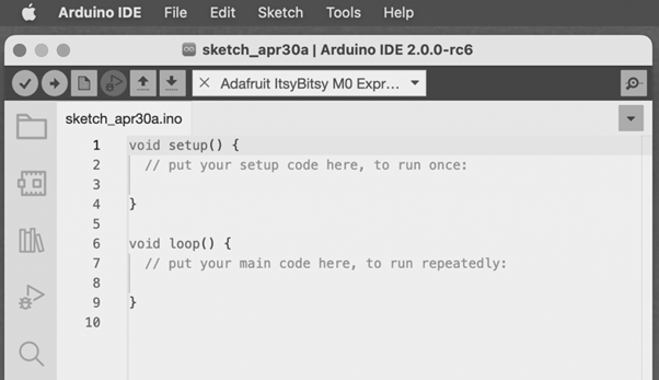
Coding Screen Image Credit-Arduino IDE:https://www.arduino.cc/en/software
It is important to note that the setup and loop blocks must have statements that are enclosed within curly brackets. Depending on the type of project you are working on, you can initialize the setup in setup() and define other necessary statements in the loop() block. Let us study each section individually
For example
void setup ( ) {
Coding statement 1;
Coding statement 2;
Coding statement n;
}
void loop ( ) {
Coding statement 1;
Coding statement 2;
Coding statement n;
}
Setup
Setup contains the very beginning section of the code that must be executed first. The pin modes, libraries, variables, etc., are included in the setup section so that no problem occurs when the remaining code runs. It is executed only once during the uploading of the program and after resetting or powering up the Arduino board.
Zero setup () resides at the top of each sketch. When the program runs after completion, it heads towards the setup section to initialize the setup and include all the necessary libraries all at once.
Loop
The loop contains statements that are executed repeatedly. Unlike, the setup section there is no restriction on running this code once, it can run multiple times according to the value of variables.
Time
The basic unit of measuring time in Arduino programming is a millisecond.
1 sec = 1000 milliseconds
Timing adjustments can be made in milliseconds. A better explanation for this can be that a 2-second delay corresponds to 2000 milliseconds.
Example
A simple example of blinking the LED using Arduino is considered.
The steps are:
- Go to the menu bar. Click on the File button in the bar.
- Click on the Examples in the menu bar.
- Click on the Basics option.
- You will see Blink, click it.
This is the window that opens:
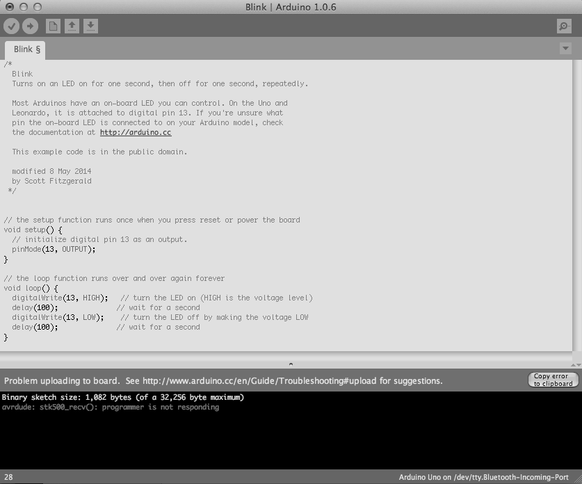
Blinking the LED Image Credit-Arduino IDE:https://www.arduino.cc/en/software
Note: The pinMode will be the main function in the void setup() and digitalWrite( ) and delay ( ) will be the main function in the void setup()
PinMode ( )
The pinMode() function assigns a specific PIN as either INPUT or OUTPUT.
The Syntax is:
pinMode (pin, mode)
Pin: It is used to specify the PIN which depends on the project requirements.
Mode: Depending on whether the pin is taking INPUT or OUTPUT, it specifies the pin's function.
Let's consider a situation to understand the pinMode. We want to take input from the PIN 13 and then,
Code:
pinMode (13, INPUT);
PinMode in OUTPUT mode
Setting pinMode to OUTPUT is important for some pins. This mode allows the specified PIN to supply sufficient current to another circuit to activate the sensor or light the LED. When set to OUTPUT, this pin goes into a very low impedance state, making the current useful. It is important to note that excessive current or short circuits between pins can damage the Atmel chip. This explains the need for setting the mode to OUTPUT.
PinMode in INPUT mode
When digitalWrite() is used, selecting the INPUT mode for any pin turns off the low state and sets the high state as the ultimate state. The INPUT mode can be employed alongside an external pull-down resistor. For this purpose, pinMode should be set to INPUT_PULLUP. This configuration reverses the behavior of the INPUT mode. In INPUT_PULLUP mode, a sufficient current is provided to light an LED connected to the pin dimly. If the LED emits a dim light, it signifies that this condition is operational.
Given these considerations, it's advisable to set the pin to OUTPUT mode to ensure proper functionality.
digitalWrite( )
The digitalWrite( ) function is used to decide the value of the pin. It can be set as either of the two values, HIGH or LOW.
HIGH: For a board that is supplied with a maximum of 1V, it results in a 5V value whereas on a board with other values like 6V, it updates the value to 6V.
LOW: It sets the pin to the ground by setting a reference of 0V.
If no pin is set with pinMode as OUTPUT, the LED may light dim.
The syntax is:
digitalWrite( pin, value HIGH/LOW)
Pin: We can specify the PIN or the declared variable.
Let's understand with an example.
Example:
digitalWrite (6, HIGH);
digitalWrite (6, LOW);
The HIGH will be used for setting the pin at number 6 high and it will ultimately turn on the LED if connected to this pin while, the LOW will be used for setting the pin at number 6 low and it will ultimately turn off the LED if connected to this pin.
delay ( )
The delay() function serves as a tool to halt program execution for a specified duration, measured in milliseconds. We have seen how delay(5000) signifies a stop of 5 seconds.
This can be understood by the fact that 1 second equals 1000 milliseconds.
Code:
digitalWrite (12, HIGH);
delay (5000);
digitalWrite (12, LOW);
delay (2000);
The program here is that the LED is connected to the pin having PIN 12 and it will remain lit for 5 seconds before turning and then will go off. The LED will then be turned off for 2 seconds as specified by delay(). This cycle will continue in a loop depending on the defined variables within the void loop() function.
Solved Example
Let us try to code the control of the LED on PIN 12, by designing it to remain ON for 3 seconds and remain OFF for 2.5 seconds. Here is the code
Pseudocode:
Firstly, we will need to set a particular pin as the output pin therefore, we will set the pin number 12 as the input in setup() block.
Then we need to set the pin number 12 high using the digitalWrite() function.
Then we use the delay() function to keep the LED on for 3 seconds.
Then we need to set the pin number 12 low using the digitalWrite() function.
Then we use the delay() function to keep the LED off for 2.5 seconds.
Code:
void setup ()  {
      pinMode ( 12, OUTPUT);               // to set the OUTPUT mode of pin number 13.
}
void loop ()  {
    digitalWrite (12, HIGH);
    delay (3000);                                                 // 3 seconds = 3 x 1000 milliseconds
   digitalWrite (12, LOW);
   delay (2500);                                               // 2.5 seconds = 2.5 x 1000 milliseconds
}
Advantages and Disadvantages of Arduino
Advantages of Arduino
We need to know the reason for selecting Arduino over other devices so let us study some advantages of Arduino.
- Arduino is the best choice for starting your programming journey in electronics. Its easy-to-use interface allows users to build simple projects on their own.
- There is no need for experience or hands-on experience in electronics before starting work on Arduino. Anyone with a genuine interest in Arduino can begin learning through simple tutorials and some guidance. These tutorials are available free of cost for creating some beginner-level and advanced projects.
- Arduinos offer a wide range of options. You can use Arduino alone to create some projects or you can add some extra features by integrating it with other devices like Raspberry Pie.
- Arduino is an open-source tool that can be accessed from different locations and platforms. Due to the inexpensive nature of Arduinos, they can be used on different microcontrollers like Atmel's ATMEGA 16U2 microcontrollers.
- Depending on the need of your project, you can avail of any Arduino that satisfies the needs. These Arduino are available in different designs that offer different size ranges, power, and specifications.
Disadvantages of Arduino
Let us see some limitations associated with Arduino:
- Despite being able to communicate with other boards like Raspberry pies and other Arduinos, the communication of Arduino is very restricted since it is installed to use certain basic communication protocols.
- Arduinos have been designed for beginner-level projects as a result they have Limited Memory and Processing Power which limits the projects that can be made using Arduino.
- Due to the lack of excess security in Arduino boards, they can be easily hacked which can result in loss and data leakage.
- When it comes to accuracy, the Arduino board is not the best choice since it lacks the precision needed for analog to digital conversion.
- Arduino responds and coordinates tasks based on the responsiveness of other components due to which it can not be programmed for real-time applications.
Application of Arduino
Arduino finds its applications in various fields due to their ability to perform different things. Let us see some of its applications:
- Arduinos are used in 3D printing where they perform the task of selecting how the printing will be performed.
- Arduinos are used for creating basic designs by makers, designers, hackers, and creators across the globe to create some great projects. Some of the projects are Laser Turret Midi Controller, Retro Gaming With an OLED Display, and Traffic Light Controller.
- Arduinos are used in the field of robotics for programming robots and adding basic features like sensing and responding to environmental conditions.
- Arduino is used in IoT(Internet of Things) since it can collect information using sensors. The collected data is then processed and transmitted for developing various smart devices.
Conclusion
We have seen how Arduino can be used for programming electronic devices using IDEs and programming languages. We have also learned some basic commands that are required for setting the input and output pins in the Arduino board. Some important coding terms like 'delays' have been introduced using some example sketches. The ability of Arduino to be programmed using coding commands makes it a useful device that is used in many applications. Readers are advised to practice their coding skills through some basic projects which have been mentioned above.
Arduino Coding Basics - FAQs
How do the digitalRead() and digitalWrite() function differently from each other?
The digitalRead() function is used to take the HIGH/LOW value from a digital pin, while the digitalWrite() function is used to alot the HIGH/LOW value to a digital pin.
What function can be used if you wish to turn on or turn off the LED?
The delay() function is used to add the delay in milliseconds. The delay defines the time when a pin will be high or low.
What are the two sections that appear when you open an Arduino IDE?
The two sections of the blocks are the setup() and loop() blocks used for initializing the commands and libraries.