Sequential circuits
Question 21
How many pulses are needed to change the contents of a 8-bit up counter from 10101100 to 00100111 (rightmost bit is the LSB)?
Question 22
Which of the following input sequences will always generate a 1 at the output z at the end of the third cycle?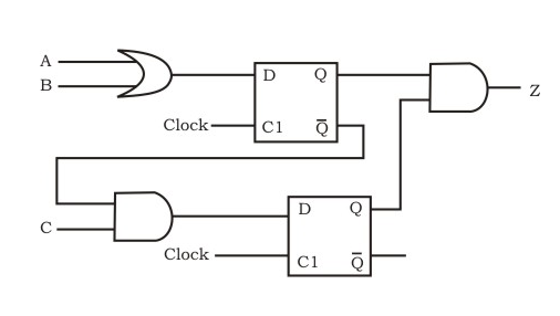
Question 23
We want to design a synchronous counter that counts the sequence 0-1-0-2-0-3 and then repeats. The minimum number of J-K flip-flops required to implement this counter is Note : This question was asked as Numerical Answer Type.
Question 24
Which of the following input sequences for a cross-coupled R-S flip-flop realized with two NAND gates may lead to an oscillation ?
Question 25
The Boolean function f implemented in the figure shown below, using two input multiplexers is:
[caption width="800"]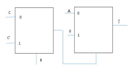 [/caption]
Question 26
A D flip-flop is to be connected to an 8085 microprocessor chip as a 1-bit output port with a port address of FF hex. Data bit D3 should be involved in the data transfer from CPU to the flip-flop. The flip-flop should be cleared on power ON.
- a. Using only one NAND gate (fan in of 10), one NOT gate and one D flip-flop. Draw the required interface logic circuit (only the relevant signals should be shown).
- b. Write a program to generate a square wave on the output of the flip-flop. ON and OFF periods of the square wave should be 7 bus cycles each.
Question 27
Design a synchronous counter to go through the following states:
1, 4, 2, 3, 1, 4, 2, 3, 1, 4,...........
Question 28
Consider the synchronous sequential circuit in the below figure
 a) Draw a state diagram, which is implemented by the circuit. Use the following names for the states corresponding to the values of flip-flops as given below.
 b) Given that the initial state of the circuit is S4, identify the set of states, which are not reachable.
a) Draw a state diagram, which is implemented by the circuit. Use the following names for the states corresponding to the values of flip-flops as given below.
b) Given that the initial state of the circuit is S4, identify the set of states, which are not reachable.Question 29
Consider following counters: Counter-1:  Counter-2:
  Which of the following option is correct?
Question 30
Consider the following statements regarding counters:
S1 : The Hamming distance of an Overbeck counter is 1
     and the Hamming distance of a Johnson counter is 2.
S2 : Only output sequence 0, 8, 12, 14, 15, 7, 3, 1, 0, ... is possible
     in Overbeck counter but not output sequence 2, 1, 8, 4, 2, 1, ...
S3 : A binary counter can represent 2^N states,
     where N is the number of bits in the code,
     whereas an Overbeck counter can represent only N states
     and a Johnson counter can represent only 2N states.
There are 46 questions to complete.
Last Updated :
Take a part in the ongoing discussion