Combinational Circuits
Question 31
A ROM is used to store the table for multiplication of two 8-bit unsigned integers. The size of ROM required is
Question 32
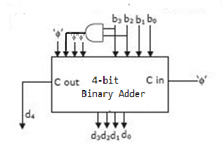
Consider the circuit given below which has a four bit binary number b3b2b1b0 as input and a five bit binary number d4d3d2d1d0 as output. The circuit implements:
 .
.
.
Question 34
A logic network has two data inputs A and B, and two control inputs C0 and C1. It implements the function F according to the following table.
 .
Implement the circuit using one 4 to 1 Multiplexer, one 2-input Exclusive OR gate, one 2-input AND gate, one 2-input OR gate and one Inverter.
.
Implement the circuit using one 4 to 1 Multiplexer, one 2-input Exclusive OR gate, one 2-input AND gate, one 2-input OR gate and one Inverter.
.
Implement the circuit using one 4 to 1 Multiplexer, one 2-input Exclusive OR gate, one 2-input AND gate, one 2-input OR gate and one Inverter. The value of F is:
 The value of F is :
Question 37
A 32 bit adder is formed by cascading 4 bit CLA adder. The gate delays (latency) for getting the sum bits is
There are 55 questions to complete.
Last Updated :
Take a part in the ongoing discussion