GATE-CS-2002
Question 26
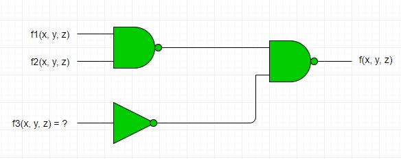
Consider the following logic circuit whose inputs and function and output is f.
 Given that
Given that
f1(dx, y, z) = ∑(0, 1, 3, 5),
f2(dx, y, z) = ∑(6, 7) and
f(dx, y, z) = ∑(1, 4, 5),
f3 is :
Question 27
Consider the following multiplexor where 10, 11, 12, 13 are four data input lines selected by two address line combinations A1A0 = 00, 01, 10, 11 respectively and f is "the output of the multiplexor. EN is the enable input.
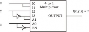 The function f(x, y, z) implemented by the above circuit is :
 The function f(x, y, z) implemented by the above circuit is :
Question 29
What are the states of the Auxiliary Carry (AC) and Carry Flag (dCY) after executing the following 8085 program?
   MVI L, 5DH
   MVI L, 6BH
   MOV A, H
   ADD L
Question 30
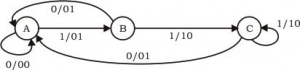
The Finite state machine described by the following state diagram with A as starting state, where an arc label is x / y and x stands for 1-bit input and y stands for 2- bit output

There are 50 questions to complete.
Last Updated :
Take a part in the ongoing discussion