What is Scrambling in Digital Electronics ?
Last Updated :
17 Mar, 2023
A computer network is designed to send information from one point to another. Data that we send can either be digital or analog. Also, signals that represent data can also be digital or analog. Thus to send data by using signals, we must be able to convert the data into signals, this conversion can be Analog to Analog, Analog to Digital, Digital to Analog, or Digital to Digital. Digital to Digital conversion involves three techniques – Line Coding, Block Coding, and Scrambling. Line Coding is always needed, whereas Block Coding and Scrambling may or may not be needed depending upon the need. Scrambling is a technique that does not increase the number of bits and does provide synchronization. The problem with techniques like Bipolar AMI(Alternate Mark Inversion) is that continuous sequence of zero’s create synchronization problems one solution to this is Scrambling.
Prerequisite: Block Coding, Line Coding
There are two common scrambling techniques:
- B8ZS(Bipolar with 8-zero substitution)
- HDB3(High-density bipolar3-zero)
B8ZS(Bipolar with 8-zero substitution): This technique is similar to Bipolar AMI except when eight consecutive zero-level voltages are encountered they are replaced by the sequence, “000VB0VB”.
Note:
- V(Violation), is a non-zero voltage which means the signal has the same polarity as the previous non-zero voltage. Thus it is a violation of the general AMI technique.
- B(Bipolar), is also a non-zero voltage level that is in accordance with the AMI rule (i.e., opposite polarity from the previous non-zero voltage).
Example: Data = 100000000
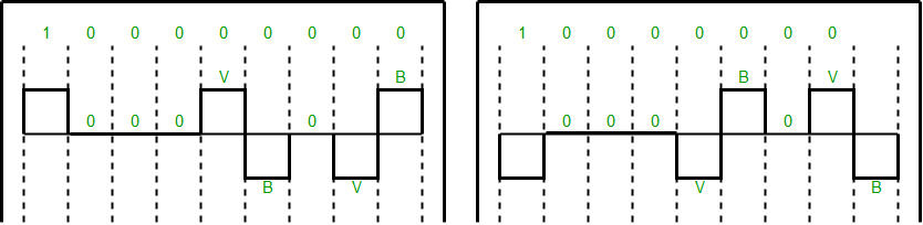
Note: Both figures (left and right one) are correct, depending upon the last non-zero voltage signal of the previous data sequence (i.e., sequence before current data sequence “100000000”).
HDB3(High-density bipolar3-zero): In this technique, four consecutive zero-level voltages are replaced with a sequence “000V” or “B00V”. Rules for using these sequences:
- If the number of nonzero pulses after the last substitution is odd, the substitution pattern will be “000V”, this helps in maintaining a total number of nonzero pulses even.
- If the number of nonzero pulses after the last substitution is even, the substitution pattern will be “B00V”. Hence even the number of nonzero pulses is maintained again.
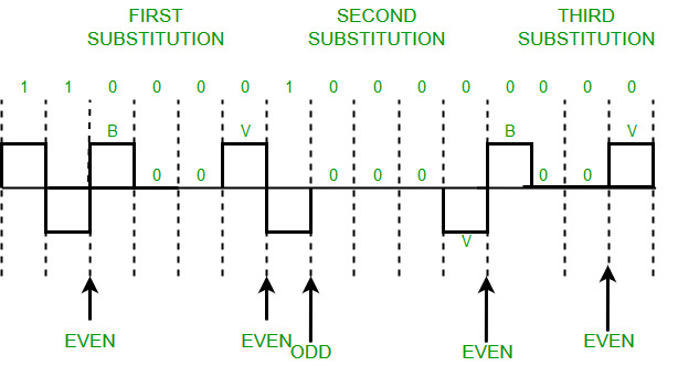
Example: Data = 1100001000000000
Output explanation: After representing the first two 1’s of data we encounter four consecutive zeros. Since our last substitutions were two 1’s(thus the number of non-zero pulses is even). So, we substitute four zeros with “B00V”.
Scrambling is a technique used in digital electronics to provide a known sequence of bits to allow for synchronization and detect errors. The code to implement scrambling will depend on the specific requirements of the system. Here is a simple example of a linear feedback shift register (LFSR) scrambler in C++:
C++
#include <bitset>
#include <iostream>
const int LFSR_LENGTH = 8;
const int TAP_POSITIONS[] = {8, 7, 6, 1};
int main() {
std::bitset<LFSR_LENGTH> lfsr;
std::cout << "Enter the starting state of the LFSR: ";
std::cin >> lfsr;
for (int i = 0; i < 32; ++i) {
int feedback = 0;
for (const auto tap_position : TAP_POSITIONS) {
feedback ^= lfsr[tap_position];
}
lfsr = (lfsr << 1) | feedback;
std::cout << lfsr << std::endl;
}
return 0;
}
|
Java
import java.util.Arrays;
public class Main {
static final int LFSR_LENGTH = 8;
static final int[] TAP_POSITIONS = {8, 7, 6, 1};
public static void main(String[] args) {
String lfsrStr;
System.out.println("Enter the starting state of the LFSR: ");
lfsrStr = System.console().readLine();
Long lfsr = Long.parseLong(lfsrStr, 2);
for (int i = 0; i < 32; ++i) {
int feedback = 0;
for (int tap_position : TAP_POSITIONS) {
feedback ^= (lfsr >> tap_position) & 1;
}
lfsr = (lfsr << 1) | feedback;
System.out.println(Long.toBinaryString(lfsr));
}
}
}
|
C#
using System;
public class MainClass
{
static readonly int LFSR_LENGTH = 8;
static readonly int[] TAP_POSITIONS = {8, 7, 6, 1};
public static void Main(string[] args)
{
string lfsrStr;
Console.WriteLine("Enter the starting state of the LFSR: ");
lfsrStr = Console.ReadLine();
long lfsr = Convert.ToInt64(lfsrStr, 2);
for (int i = 0; i < 32; ++i)
{
int feedback = 0;
foreach(int tap_position in TAP_POSITIONS)
{
feedback ^= (int)(lfsr >> tap_position) & 1;
}
lfsr = (lfsr << 1) | feedback;
Console.WriteLine(Convert.ToString(lfsr, 2));
}
}
}
|
The output of this code will be the scrambled sequence generated by the linear feedback shift register (LFSR) for 32 clock cycles. The exact output will depend on the starting state of the LFSR, which is entered by the user. Here is an example of the output for a starting state of 01100101:
Enter the starting state of the LFSR: 01100101
11000100
01100010
10100010
01010001
10101000
01010100
10101010
01010101
10101101
01011010
10101111
01011110
10111100
01111000
11100000
01000000
10000000
00000000
00000000
00000000
00000000
00000000
00000000
00000000
00000000
00000000
00000000
00000000
00000000
In this example, the LFSR is initialized with an 8-bit state. The TAP positions, which determine the feedback taps in the LFSR, are specified as {8, 7, 6, 1}. The LFSR is then clocked 32 times to generate the scrambled sequence. The output will be the scrambled sequence, where each line represents the state of the LFSR after each clock cycle.
Note: Zero non-zero pulses are also even.
Like Article
Suggest improvement
Share your thoughts in the comments
Please Login to comment...