Transition Table in Automata
Last Updated :
10 Sep, 2021
Transition Table :
Transition function(∂) is a function which maps Q * ∑ into Q . Here ‘Q’ is set of states and ‘∑’ is input of alphabets. To show this transition function we use table called transition table. The table takes two values a state and a symbol and returns next state.
A transition table gives the information about –
- Rows represent different states.
- Columns represent input symbols.
- Entries represent the different next state.
- The final state is represented by a star or double circle.
- The start state is always denoted by an small arrow.
Example 1 –
This example shows transition table for NFA(non-deterministic finite automata) .
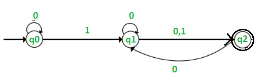
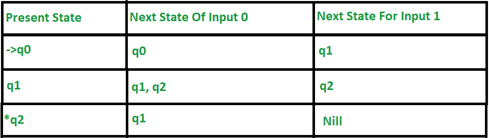
Explanation of above table –
- First column indicates all the present states ,Next for input 0 and 1 respectively.
- When the present state is q0, for input 0 the next state will become q0. For input 1 the next state is q1.
- When the present state is q1, for input 0 the next state is q1 or q2, and for 1 input the next state is q2.
- When the current state is q2 for input 0, the next state will become q1, and for 1 input the next state will become Nil.
- The small straight arrow on q0 indicates that it is a start state and circle on to q3 indicates that it is a final state.
Example 2 –
This example shows transition table of DFA(deterministic finite automata).
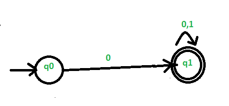
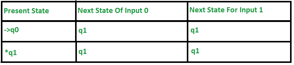
Explanation of above table –
- First column indicates all the present states, Next for input 0 and 1 respectively.
- When the current state is q0, for input 0 the next state will become q1 and for input as 1 the next state is q1.
- When the current state is q1, for input 0, the next state will become q1, and on 1 input the next state is q1.
- The small straight arrow on q0 indicates that it is a start state and circle on to q3 indicates that it is a final state.
Example 3 –
This example shows transition table of DFA(deterministic finite automata)
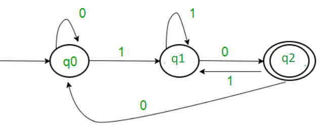
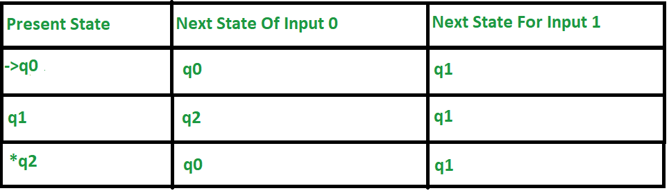
Explanation of above table –
- First column indicates all the present states, Next for input 0 and 1 respectively.
- When the current/present state is q0, for input 0 the next state will become q0 and for input 1 the next state is q1.
- When the current state is q1, on input 0, the next state will become q2, and for 1 input the next state is q1.
- When the current state is q2 for input 0, the next state will become q0, and for 1 input the next state is q1.
- The small straight arrow on q0 indicates that it is a start state and circle on to q3 indicates that it is a final state.
Example 4 –
This example shows transition table for NFA(non-deterministic finite automata).
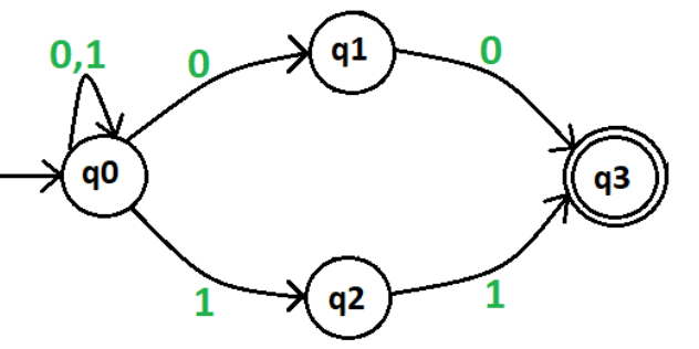
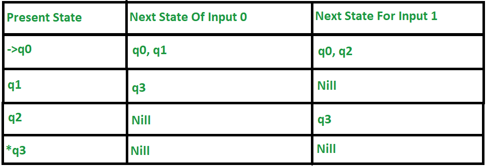
Explanation of above table –
- First column indicates all present states, Next for input 0 and 1 respectively.
- When the current state is q0, for input 0 next state will become q0 or q1 and for input 1 the next state is q0 or q2.
- When the current state is q1, for input 0 next state will become q3, and for input 1 the next state is Nil as there is no state for input 1.
- When the current state is q2 for input 0, next state will become nil as there is no state for input 0, and for 1 input the next state will become q3.
- When the current state is q3 for input 0, next state will become nil as there is no state for input 0, and for 1 input the next state will also become nil as there is no state for input 1.
- The small straight arrow on q0 indicates that it is a start state and circle on to q3 indicates that it is a final state.
Note – There can be multiple final states in both DFA and NFA but initial state is unique.
Like Article
Suggest improvement
Share your thoughts in the comments
Please Login to comment...