Torque on a Rectangular Current Loop
Last Updated :
08 Mar, 2022
Torque is the force that can cause an object to twist around an axis. Force is what causes an object to accelerate in linear kinematics. Angular acceleration is also caused by torque. As a result, torque can be defined as the rotating equivalent of a linear force. The point at which the item rotates is known as the axis of rotation. In physics, torque is the tendency of a force to turn or twist. Torque can be expressed in a variety of ways, including moment and moment of force. In this post, we’ll look at how to calculate the torque on a current-carrying rectangular wire loop in a uniform magnetic field.
Torque on a Rectangular Current loop
Consider a rectangular loop that carries a current of magnitude I. When placed in a magnetic field, this loop experiences a torque but no net force, similar to what an electric dipole experiences in a homogeneous electric field. Consider the case where the rectangular loop is in the same plane as the magnetic field B. The loop’s arms that are parallel to the magnets receive no force from the field, but the arms that are perpendicular to the magnets receive a force equal to F1.
F1 = IbB
This force is directed in the plane’s direction. In the same way, we may write the formula for a force F2 applied to the arm CD.
F2 = IbB = F1
The loop’s torque is given by, and the loop’s net force is zero.
τ = F1(a/2) + F2(a/2)
= IbB(a/2) + IbB(a/2)
= I(ab)B
τ = IAB
The area of the rectangle is ab. The loop rotates in an anti-clockwise manner due to the torque.
Consider the situation where the plane of the loop is not parallel to the magnetic field. Let be the angle generated by the field, and let be the coil’s normal is given by θ. The forces acting on the arms BC and DA will always be equal in size and will always act in opposite directions, as can be seen. The results of these forces cancel out because they are equal opposites and collinear at all points, resulting in zero-force or torque. The forces on the arms AB and CD are determined by F1 and F2. These forces are similar in size and direction and can be produced by,
F1 = F2 = IbB
Because these forces are not collinear, the pair on the coil, causes a torque. The magnitude of the torque can be computed using,
τ = F1(a/2) sin θ + F2(a/2) sin θ
= I(ab)B sin θ
τ = IAB sin θ
Explanation for Torque on Current Loop
When you apply pressure to an object, it moves or exerts a certain amount of force. For example, spinning the cap off a bottle, removing the lid from a package, opening the doorknob, tying a shoelace, and so on. This is a rotating motion, which is a torque movement with some movement. If the concept of torque is not grasped, there will be no movement. Torque is a phrase that refers to the spinning movement that all items have and that we would be unable to operate properly without.
The formula for torque is τ = F × r because torque is equal to the twisting force that tends to induce the movement or rotation. This formula is used when force (f) is applied to an item depending on the distance (r) between the centre of rotation and the location where the force is applied. To detect the direction of the torque, pupils should curl their right-hand fingers in the direction of the current and their thumb should stick out and point to the area vector, according to the right-hand rule.
Torque on a Rectangular Current loop Equation in Vector Form
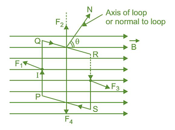
Consider a rectangular coil PQRS hanging in an induction field B with a uniform magnetic field. Let PQ = RS = l and QR = SP = b be the two variables. Let I represent the current flowing through the coil in the direction PQRS, and let θ be the angle formed by the coil’s plane with the magnetic field’s direction. The forces will act on the Coil’s four arms.
The forces vector F1 and vector F3 acting on sides PQ and RS are equal and opposing, but their paths of action are distinct, according to Fleming’s left-hand rule; thus, the resultant force of vector F1 and vector F3 is zero, but they form a couple known as the deflecting couple. The perpendicular distance between vector F1 and vector F3 is bsinθ when the normal plane of the loop makes an angle with the direction of magnetic field B.
Since, Torque, τ = IAB sinθ
So when the loop contains N-turns, then
τ = NI ABsinθ
In vector form,

The direction of the torque is perpendicular to the direction of the area of the loop as well as the direction of the magnetic field i.e., along 
Conclusion
The coil rotates along its own axis due to this torque. Its value varies according to the angle formed by the coil’s plane and the magnetic field’s direction.
- If an Electric dipole is in the electric field then torque becomes,
 , where, P is the Electric dipole moment and E is the Electric field.
 - If a Magnetic dipole is in a magnetic field then torque becomes,
 , where, M is the Magnetic dipole moment and B is the Magnetic field.
Special cases
Case 1: If the coil is parallel with the magnetic field B direction,
Then, θ = 0o and cos θ = 1. We have,
τ = nIBA cos θ
= nIBA cos 0
= nIBA
∴ τ = nIBA (Maximum)
Case 2: If the coil is perpendicular with the magnetic field B direction,
Then, θ = 90o and cos θ = 0.
τ = nIBA cos θ
= nIBA cos 90
= nIBA (0)
∴ τ = 0 (Minimum)
Sample Problems
Problem 1: What is the maximum torque that a 40 cm wide handle can create when released by a 2N force at its edge?
Solution:
Given that: F = 2 N,
d = 40 cm = 0.40 m
τ = F × d
= 20 × 0.40
= 8 N-m
Problem 2: A torque of magnitude of 4.5 × 10⁻² J is experienced by a short bar magnet with its axis at 30o and a uniform external magnetic field of 0.25 T. How large is the magnet’s magnetic moment?
Solution:
Given that:
τ = 4.5 × 10⁻² J,
θ = 30o,
B = 0.25 T
We have,
τ = MB sin θ
4.5 × 10-2 = M × 0.25 sin 30o
∴ M = 0.36 J/T
Problem 3: An electric dipole with a 2 × 10⁵ N/C intensity is set at a 30o angle. A torque of 4 Nm is experienced by it. The dipole has a charge of 2 cm on it.
Solution:
Given that:
E = 2 × 10⁵ N/C,
τ = 4 Nm,
l = 2 cm = 0.02 m
We have,
τ = pE sin θ
4 = p × 2 × 10⁵ × sin θ
p = 4 × 10⁻⁵ Cm
q = p/l
q = (4 × 10⁻⁵)/0.02
q = 2 mC
Problem 4: In a homogeneous magnetic field of strength 0.8 Weber/m2, a rectangular coil of length 0.56 m and width 0.2 m with 40 turns of wire are suspended vertically. A current of 6 A flows across the coil. The torque necessary to keep the coil in stable equilibrium will be if the coil plane is inclined at a 90o angle with the field direction.
Solution:
M = NIπr2
= 40 × 6 × 0.56 × 0.2
= 26.88
B = 0.8 T
We have,
τ = MB sin θ
= 26.88 × 0.8 sin 90o
= 21.504 Nm
Problem 5: If a door has a width of 80 cm and is released by a force of 2 N at its edge, calculate the torque produced by the door.
Solution:
Given that:
F = 2 N,
d = 80 cm = 0.80 m
τ = F × d
= 20 × 0.80
= 16 Nm
Problem 6: A short bar magnet with its axis at 90o and a uniform external magnetic field of 0.27 T experiences a torque of magnitude 2.51 × 10² J. What is the magnetic moment of the magnet?
Solution:
Given that:
τ = 2.51 × 10² J,
θ = 90o,
B = 0.27 T
We have,
τ = MB sin θ
2.51 × 102 = M × 0.27 sin 90o
M = 929 J/T
Problem 7: Obtains a torque expression for a rectangular current carrying look in a uniform magnetic field B. Indicate which way the loop is being torqued.
Solution:
Consider a rectangular coil PQRS hanging in an induction field B with a uniform magnetic field. Let PQ = RS = l and QR = SP = b be the two variables. Let I represent the current flowing through the coil in the direction PQRS, and let θ be the angle formed by the coil’s plane with the magnetic field’s direction. The forces will act on the Coil’s four arms.
The forces vector F1 and vector F3 acting on sides PQ and RS are equal and opposing, but their paths of action are distinct, according to Fleming’s left-hand rule; thus, the resultant force of vector F1 and vector F3 is zero, but they form a couple known as the deflecting couple. The perpendicular distance between vector F1 and vector F3 is bsinθ when the normal plane of the loop makes an angle with the direction of magnetic field B.
Since, Torque, τ = IAB sinθ
So when the loop contains N-turns, then
τ = NI ABsinθ
In vector form,
The direction of the torque is perpendicular to the direction of the area of the loop as well as the direction of the magnetic field i.e., along
Like Article
Suggest improvement
Share your thoughts in the comments
Please Login to comment...