Three-State Bus Buffers
Last Updated :
06 Oct, 2021
Usually, any logic circuit has 2 states, i.e., in binary form (0 and 1). The buffer exhibits three states. It has 3 pins which include:
Input – accepts 1 or 0 (0 – disable and 1 – enable)
Output – if 3-state control is 0 then output follows input(according to the input 0 and 1).
Definition:
A three-state bus buffer is an integrated circuit that connects multiple data sources to a single bus. The open drivers can be selected to be either a logical high, a logical low, or high impedance which allows other buffers to drive the bus.
Now, let’s see the more detailed analysis of a 3-state bus buffer in points:
- As in a conventional gate, 1 and 0 are two states.
- The third state is a high impedance state.
- The third state behaves like an open circuit.
- If the output is not connected, then there is no logical significance.
- It may perform any type of conventional logic operations such as AND, OR, NAND, etc.
Difference between normal buffer and three-state buffer:
It contains both normal input and control input. Here, the output state is determined by the control input.
- When the control input is 1, the output is enabled and the gate will behave like a conventional buffer.
- When the control input is 0, the output is disabled and the gate will be in a high impedance state.
More Points:
- To form a single bus line, all the outputs of the 4 buffers are connected together.
- The control input will now decide which of the 4 normal inputs will communicate with the bus line.
- The decoder is used to ensure that only one control input is active at a time.
- The diagram of a 3-state buffer can be seen below.
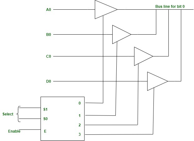
Figure – Bus Line with three-state -buffers
Like Article
Suggest improvement
Share your thoughts in the comments
Please Login to comment...