Steps to Analyze and Design Object Oriented System
Last Updated :
17 May, 2021
Object Oriented Analysis (OOA) :
Object-Oriented Analysis (OOA) is the first technical activity performed as part of object-oriented software engineering. OOA introduces new concepts to investigate a problem.
Object Oriented Design (OOD) :
An analysis model created using object-oriented analysis is transformed by object-oriented design into a design model that works as a plan for software creation. OOD results in a design having several different levels of modularity i.e., The major system components are partitioned into subsystems (a system-level “modular”), and data their manipulation operations are encapsulated into objects (a modular form that is the building block of an OO system.).

steps/stages in the analysis and design of an object-oriented system
There are various steps/stages in the analysis and design of an object-oriented system as given in below figure :
- Create a Use case model :
The first step in the analysis and design of an object-oriented system is to recognize the actors interlinked with the system. After that, create the use case and draw the use case diagram.
- Draw activity diagram (If required) :
The activity Diagram demonstrates the dynamic nature of a system by creating the flow of control form activity. An activity addresses a procedure on some class in the framework that outcomes in an adjustment of the condition of the system. The below figure shows the activity graph handling a request to convey a few products.
- Draw the interaction diagram :
A interaction diagram shows a collaboration, comprising a bunch of articles and their relationship, including the messages that might be dispatched among them. Interaction diagram address the unique perspective on a system.
Steps for drawing interaction diagrams :
- Initially, we ought to distinguish that the objects as for each use case.
- Then we draw the sequence diagrams for each use case.
- Then we draw the collaboration diagrams for each use case.
- Draw the class diagram : The class diagram is responsible for showing the relationship between the classes. There are four types of relationships available in class diagrams :
- Association –
It is a semantic connection between classes. At the point when an association associates two classes, each class can send messages to the next in sequence or a collaboration diagram. They may be bi-directional or unidirectional in nature.
- Dependencies –
They connect two classes and are always unidirectional in nature and display that one class, depends on the definitions of another class.
- Aggregations –
They are a stronger form of association that shows the relationship between a whole and its parts.
- Generalizations –
They are used to display an inheritance relationship between the two classes.
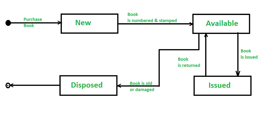
- Design of State chart diagrams :
A state chart is utilized to show the state space of a given class, the occasion that influences progress starting with one state then onto the next, and the activity that outcome from a state change. A state change graph for a “book” in the library management system is shown below :
6. Draw component and development diagram :
These diagrams address the static execution perspective on a system they are identified with class diagrams in that a segment ordinarily guides to at least one class, interface, or coordinated effort.
Share your thoughts in the comments
Please Login to comment...