Control Flow Graph (CFG) – Software Engineering
Last Updated :
07 Jan, 2024
A Control Flow Graph (CFG) is the graphical representation of control flow or computation during the execution of programs or applications. Control flow graphs are mostly used in static analysis as well as compiler applications, as they can accurately represent the flow inside a program unit. The control flow graph was originally developed by Frances E. Allen..
Characteristics of Control Flow Graph
- The control flow graph is process-oriented.
- The control flow graph shows all the paths that can be traversed during a program execution.
- A control flow graph is a directed graph.
- Edges in CFG portray control flow paths and the nodes in CFG portray basic blocks.
There exist 2 designated blocks in the Control Flow Graph:
- Entry Block: The entry block allows the control to enter into the control flow graph.
- Exit Block: Control flow leaves through the exit block.
Hence, the control flow graph comprises all the building blocks involved in a flow diagram such as the start node, end node and flows between the nodes.
General Control Flow Graphs
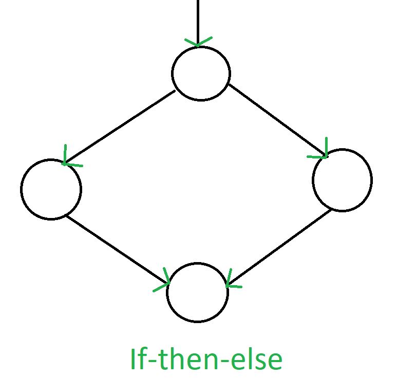
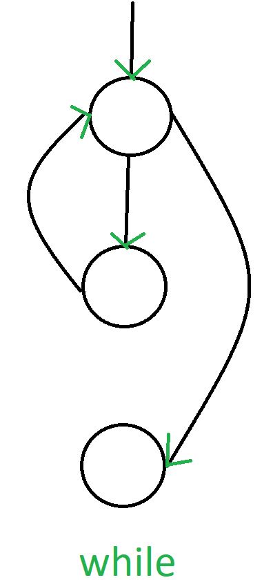
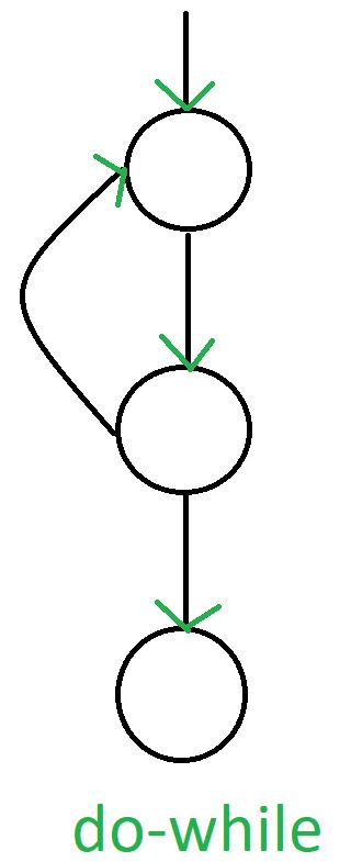
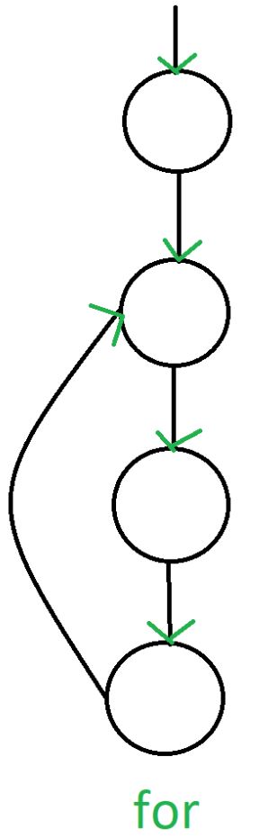
Control Flow Graph is represented differently for all statements and loops. Following images describe it:
1. If-else
2. While
3. do-while
4. for
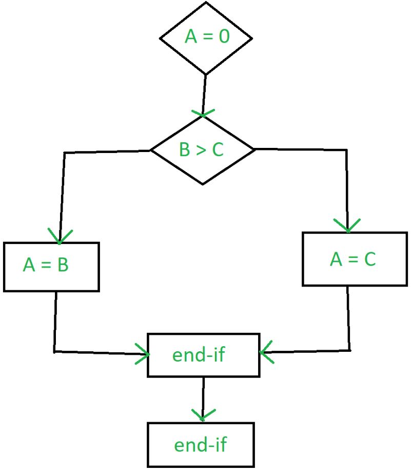
Example
if A = 10 then
if B > C
A = B
else A = C
endif
endif
print A, B, C
Flowchart of above example will be:
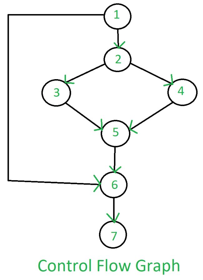
Control Flow Graph of above example will be:
Advantage of CFG
There are many advantages of a control flow graph.
- It can easily encapsulate the information per each basic block.
- It can easily locate inaccessible codes of a program and syntactic structures such as loops are easy to find in a control flow graph.
Like Article
Suggest improvement
Share your thoughts in the comments
Please Login to comment...