Sequential circuits
Question 1
Consider the following circuit involving three D-type flip-flops used in a certain type of counter configuration.
[caption width="800"]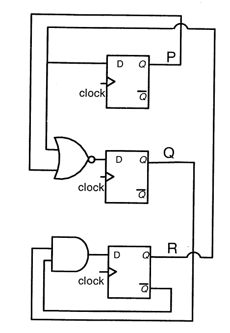 [/caption]
If at some instance prior to the occurrence of the clock edge, P, Q and R have a value 0, 1 and 0 respectively, what shall be the value of PQR after the clock edge?
Question 2
Consider the data given in previous question. If all the flip-flops were reset to 0 at power on, what is the total number of distinct outputs (states) represented by PQR generated by the counter?
Question 3
In the sequential circuit shown below,if the initial value of the output Q1Q0 is 00,what are the next four values of Q1Q0?
[caption width="800"] [/caption]
Question 4
The control signal functions of a 4-bit binary counter are given below (where X is “don’t care”) The counter is connected as follows: 
The counter is connected as follows:  Assume that the counter and gate delays are negligible. If the counter starts at 0, then it cycles through the following sequence:
Question 5
You are given a free running clock with a duty cycle of 50% and a digital waveform f which changes only at the negative edge of the clock. Which one of the following circuits (using clocked D flip-flops) will delay the phase of f by 180°?
[caption width="800"] [/caption][caption width="800"]
 [/caption]
Question 6
Let k = 2n. A circuit is built by giving the output of an n-bit binary counter as input to an n-to-2n bit decoder. This circuit is equivalent to a
Question 7
[caption width="800"]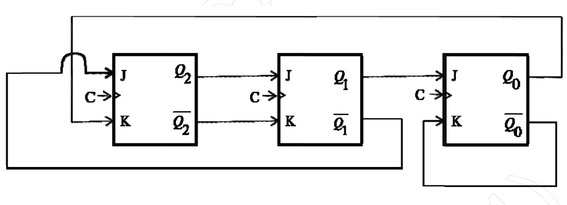 [/caption]
[/caption]
The above sequential circuit is built using JK flip-flops is initialized with Q2Q1Q0 = 000. The state sequence for this circuit for the next 3 clock cycle is
Question 8
Consider the circuit in the diagram. The ⊕ operator represents Ex-OR. The D flipflops are initialized to zeroes (cleared). 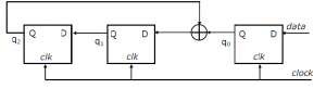
The following data: 100110000 is supplied to the “data” terminal in nine clock cycles. After that the values of q2q1q0 are:
Question 9
Consider the following circuit involving a positive edge triggered D FF. 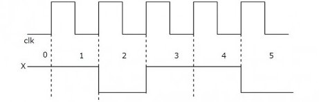
Consider the following timing diagram.
Let Ai represent the logic level on the line A in the i-th clock period.
Let A\' represent the complement of A. The correct output sequence on Y over the clock periods 1 through 5 is
Question 10
Consider the following circuit. 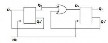
The flip-flops are positive edge triggered D FFs. Each state is designated as a two bit string Q0Q1. Let the initial state be 00. The state transition sequence is:
 A)
B)
C)
D)
There are 46 questions to complete.
Last Updated :
Take a part in the ongoing discussion