Phasor analysis is used to determine the steady-state response to a linear circuit functioning on sinusoidal sources with frequency (f). It is very common. For example, one can use phasor analysis to differentiate the frequency response of a circuit by performing phasor analysis over a range of frequencies. The circuit should be in a stable state so that any transient behavior dies away over time and the response becomes completely repetitive.
In this article, we have provided details about what are phasors, phasor analysis, its definition, diagram, and applications.
What are Phasors?
Phasor analysis computes only the steady-state behavior. The circuit should be linear, which means it is constructed from linear components like simple resistors, capacitors, and inductors. A linear component is one whose response is proportional to its input. For example, a resistor is considered linear if V = IR because voltage V, the response, is proportional to I, the input with the constant of proportionality being R.
- Amplitude,
- Phase
- Frequency.
For example, v(t) = A cos (ωt + φ)
Here A is the amplitude, φ is the phase, and f is the frequency, where ω = 2πf. In a circuit, there will be many signals but in the case of phasor analysis, they will all have the same frequency. Hence, the frequency is differentiated using only their amplitude and phase. This combination of amplitude and phase to describe a signal is the phasor for that signal.
Phasors are a mathematical tool used in engineering and physics to simplify the analysis of sinusoidal signals, which vary cyclically over time. They are instrumental in the study of electrical circuits, electromagnetism, and wave phenomena.
A sinusoidal signal can be expressed in the time domain as A sin(ωt+ϕ) or A cos(ωt+ϕ), where:
- A is the amplitude,
- ω is the angular frequency (in radians per second),
- t is time, and
- ϕ is the phase angle (in radians).
Phasors Definition
A phasor is a complex number used to represent the magnitude and phase of a sinusoidal function, particularly in the context of alternating current (AC) electricity, signal processing, and wave mechanics.
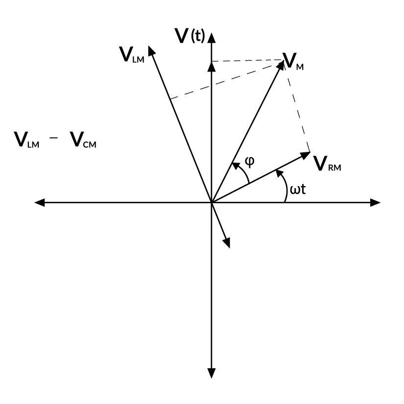
Phasor Diagram
A phasor can be a scaled line whose length determines an AC quantity that has both magnitude (peak amplitude) and direction (phase) which is frozen at some point in time. A phasor diagram is used to show the phase relationship between two or more sine waves having the same frequency. In a phasor diagram, the phasors are represented by open arrows, which rotate counterclockwise, with an angular frequency of ω about the origin.
Phasor diagram
Properties of Phasors
- The length of a phasor is proportional to the maximum value of the alternating quantity involved.
- The projection of a phasor on the vertical axis gives the instantaneous value of the alternating quantity involved.
Impedance of AC Circuit
Every component used in the circuit has an internal resistance that depends on the material used for the component. In an AC circuit, the voltage across each electrical component depends on its resistance. For the resistors used in the circuit, the voltage across it is given by Ohm’s law as, VR = I × R where I is the electric current amplitude across the resistor and R is the resistance of the element.
Whereas, in the Resistor-Inductor-Capacitor circuit, the rms voltage is given by the formula: Vrms = Z × Irms where Z is the circuit’s total resistance or the circuit impedance. In other words, the Impedance of the circuit is the total internal resistances of all circuit’s parts used in impeding or slowing down the electric current and thus delaying it from reaching the next circuit’s component. In an AC circuit, the circuit impedance is given by the formula: Z = √(R2 + (XL – XC)2) where XL and XC are the inductive reactance and the capacitive reactance respectively. XL, XC, and Z are all measured in Ohm same as the resistance R.
Application of Phasors in AC Circuits
Phasors are particularly useful in alternating current (AC) circuit analysis because they allow the use of complex algebra to solve circuits. This simplifies calculations involving sinusoidal voltages and currents with different phases. By converting time-domain signals into phasors, one can easily add or subtract voltages and currents, calculate impedances, and solve for unknowns using Ohm’s law and Kirchhoff’s laws in the frequency domain. After the calculations are complete, the results can be converted back to the time domain to interpret physically.
People Also Read:
Phasors Examples
Example 1: The phase difference between the alternating current and voltage represented by the following equation I = I0 sin ωt, E = E0 cos(ωt + π/3), will be
Solution:
Given,
I = I0 sin ωt
E = E0 cos (ωt + π/3)
= E0 sin (π/2 + (ωt + π/3)) …{since, sin((π/2) + θ = cosθ}
= E0 sin (ωt + 5π/6)
So, phase difference (φ) = 5π/6
Example 2: A coil of 200 Ω resistance and 1.0H inductance is connected to an ac source of frequency 200/2π Hz. Phase angle between potential and current will be.
Solution:
We know,
tanφ = Xl / R = 2πvL/R = (2π x 200/2π x 1)/ (200) = 1
Hence, φ = 45o.
Example 3: The current through a coil of self-inductance L = 2mH is given by i = t2e-t at time t. How long it will take to make the emf zero?
Solution:
The current is given by the relation i = t2e-t.
When the emf is zero, the current (i) will also be zero.
so we have t2e-t = 0
we set each factor equal to zero separately:
- t2 = 0 : when t=0 ,it’s not the solution because it’s the starting point.
- e-t = 0 : Exponential functions never equal zero, so this factor is not the solution.
the only solution is t = 0, which means the emf becomes zero at t = 0 . This is the starting time.
Example 4: The phase difference between the alternating current and voltage represented by the following equation I = I0 sin ωt , E = E0 cos(ωt + π/3), will be
Solution:
Given:
I = I0 sin ωt
E = E0 cos (ωt + π/3)
= E0 sin [π/2 + (ωt + π/3) ] {sin( π/2 + θ) = cosθ}
= E0 sin (ωt + 5π/6)
So, phase difference (φ) = 5π/6
Example 5: The phase difference between current and voltage is an AC circuit is π/4 radian. If the frequency of AC is 50 Hz, then the phase difference equivalent to the time difference is.
Solution:
Given:
Phase difference (φ) = π/4 rad
Frequency (f) = 50Hz
Then,
time difference (Δt) = φ / 2πf
Δt = π/4 / 2π x 50 = 1/400 = 0.0025 s
Δt = 2.5 ms
Example 6: The instantaneous values of current and emf in an ac circuit are I = (1/√2) sin 314t amp and E = √2sin(314t – π/6)V respectively. The phase difference between E and I will be.
Solution:
We know that,
Phase difference relative to the current,
φ = (314t – π/6) – (314t)
= – π/6
Example 7: A 12 Ω resistor and a 0.21 H inductor are connected in series to an a.c. source operating at 20 V. 50 cycles/second. The phase angle between the current and source voltage is
Solution:
Given:
Resistance (R) = 12 Ω
Inductance (I) = 0.21 Henry
Hence, ω = 2πf = 2π x 50 = 100π
ωL = 100π x 0.21 = 66 Ω
Reactance (Z) = √(R2 + (XL)2) = √(R2 + (ωL)2) = √(144 + 4356) = √4500 = 67.08Ω
Power factor, cos φ = R / Z = 12/67.08 = 0.1789
Phase angle = φ = cos-1(0.1789) =79.70 which is the lagging phase angle between the current and source voltage.
Summary – Phasors
Phasors are an invaluable mathematical tool in engineering and physics, especially when it comes to analyzing circuits that operate with sinusoidal signals — think waves of electricity that ebb and flow over time. Imagine trying to understand a conversation where everyone speaks at the same tone but with varying loudness and timing; that’s similar to how phasors help engineers differentiate signals in a circuit. They boil down the complex dance of alternating current (AC) signals to simpler terms of magnitude and phase, ignoring the frequency since it’s uniform across the board. Phasors transform these signals from the time realm into a more manageable frequency domain, letting us visually represent the relationship between signals as vectors or arrows in a phasor diagram. This graphical approach, along with phasor algebra, streamlines calculating how different parts of an AC circuit, like resistors, capacitors, and inductors, affect the overall flow of electricity. By understanding the impedance, or the total resistance within the circuit, engineers can predict how electricity behaves, making phasors essential for designing and troubleshooting everything from household electronics to complex power grids.
FAQs on Phasors
Define Phasor?
A phasor is a complex number used to represent the magnitude and phase of a sinusoidal function, particularly in the context of alternating current (AC) electricity, signal processing, and wave mechanics.
What are Phasor diagrams?
Phasor diagrams present a graphical representation, plotted on a coordinate system, of the phase relationship between the voltages and currents within passive components or a whole circuit. Generally, phasors are defined relative to a reference phasor which is always points to the right along the x-axis.
How to calculate circuit impedance?
To Calculate the circuit impedance (Z):
Step 1: Find the capacitor’s impedance XC and the inductor’s impedance XL then do the subtraction XL – XC.
Step 2: Square the difference (XL – XC) and add it to the square value of the resistance R.
Step 3: Square root the end result to get Z measured in Ohms.
Explain the uses of the Phasor diagram.
Uses of phasor diagram are:
- Vectors, Phasors and Phasor diagrams can only be applied to sinusoidal AC alternating quantities.
- Phasor Diagrams can be used to represent two or more stationary sinusoidal quantities at any instant in time.
- Phasor diagrams can be drawn to represent more than two sinusoids. They can be either voltage, current or some other alternating quantity but the frequency of all of them must be the same.
How to draw a phasor diagram?
There are Five Rules for Drawing Phasor Diagrams.
Rule 1: The length of the phasor is directly proportional to the amplitude of the wave depicted.
Rule 2: In circuits which have L, C, R connected in series. It is customary to draw the phasor representing current horizontally, and call this the reference phasor.
Rule 3: In parallel circuits, where L, C, and R are connected in parallel, the phasor representing the supply voltage is always drawn in the reference direction.
Rule 4: The direction of rotation of all phasors is considered to be Anticlockwise.
Rule 5: In any one diagram, the same type of value (RMS, peak, etc) is used for all phasors, not a mixture of values.
How are Phasor diagrams used to denote Phase Difference
Every phasor in the diagram will have the same angular velocity because they represent sine waves of identical frequency. The length of the each phasor arm is directly related to the amplitude of the wave it represents, and the angle between the phasors is the same as the angle of phase difference between the sine waves.
Like Article
Suggest improvement
Share your thoughts in the comments
Please Login to comment...