Multiplexer Design using Verilog HDL
Last Updated :
21 Sep, 2023
In this article, we are discussing Multiplexer Design. Below mentioned is the article in which we are going to discuss the problem.
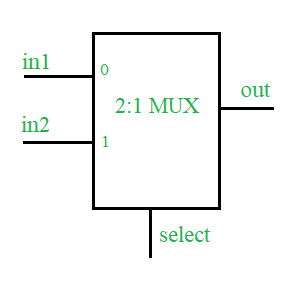
Design of a 2:1 MUX using Verilog Hardware Description Language along with Testbench.
Concepts
A multiplexer is a combinational type of digital circuit that is used to transfer one of the available input lines to a single output and, which input has to be transferred to the output will be decided by the state(logic 0 or logic 1) of the select line signal. 2:1 Multiplexer has two inputs, one select line (to select one of the two inputs), and a single output.
Truth Table
Verilog HDL code of 2:1 MUX
Design
// define a module for the design
module mux2_1(in1, in2, select, out);

// define input  port
input in1, in2, select;

// define the output port
output out;

// assign one of the inputs to the output based upon select line input
assign out = select ? in2 : in1;
endmodule :mux2_1
Testbench
module test;
reg in1, in2, select;
wire out;

// design under test
mux2_1 mux(.in1(in1), .in2(in2),
            .select(select), .out(out));

// list the input to the design
initial begin in1=1'b0;in2=1'b0;select=1'b0;
        #2    in1=1'b1;
        #2    select=1'b1;
        #2    in2=1'b1;
        #2    $stop();
        end

// monitor the output whenever any of the input changes
initial begin $monitor("time=%0d, input1=%b, input2=%b,
                       select line=%b, output=%b", $time,
                        in1, in2, select, out);
        end
endmodule :test
Expected Output
time=0, input1=0, input2=0, select line=0, out=0
time=2, input1=1, input2=0, select line=0, out=1
time=4, input1=1, input2=0, select line=1, out=0
time=6, input1=1, input2=1, select line=1, out=1
Gate level /Structural Modeling
module mux4x1_gate_level(
    input a,
    input b,
    input c,
    input d,
    input s0,
    input s1,
    output y
);

    wire n1, n2, n3, n4, n5, n6;

    not (n1, s1);
    not (n2, s0);
    and (n3, a, n1, n2);
    and (n4, b, n1, s0);
    and (n5, c, s1, n2);
    and (n6, d, s1, s0);
    or (y, n3, n4, n5, n6);

endmodule
Dataflow Modelling
module mux4x1(
    input s0,
    input s1,
    input a,
    input b,
    input c,
    input d,
    output y
);
    assign y = (a & (~s1) & (~s0)) |(b & (~s1) & s0) |(c & s1 & (~s0)) |(d & s1 & s0);

endmodule
Like Article
Suggest improvement
Share your thoughts in the comments
Please Login to comment...