Link Access Procedure, Balanced (LAPB) Frame Format
Last Updated :
11 Aug, 2020
Link Access Procedure, Balanced (LAPB) is basically a layer 2 protocol that is required in many control protocols like X.25. It was developed by ITU-T, OF Link Access Procedure (LAP) that itself comes from High-Level Data Link Control (HDLC). It runs at Layer 2 i.e. Data Link Layer (DLL) of the OSI Model.
It is generally a balanced protocol that usually operates in Asynchronous Balanced Mode (ABM). It is a bit-oriented protocol that is basically derived from HDLC. It is used to ensure that all of data frames or packets are error-free and are in the correct sequence or not. It is also capable of placing frames in the correct order and sequence and also capable as checking packets or frames for errors i.e., error detection and then relieves higher-level protocols from having to perform all of these functions. LAPB Sessions can be developed and established by either Data Terminal Equipment (DTE) or Data Circuit-Terminating Equipment (DCE).
Frame Format :
LAPB Frame usually contains a header and trailer that basically encapsulate a packet or frame formed by X.25 Packet Layer Protocol (PLP). It also provides mechanism for transporting and transmitting data frames or packets across a link.
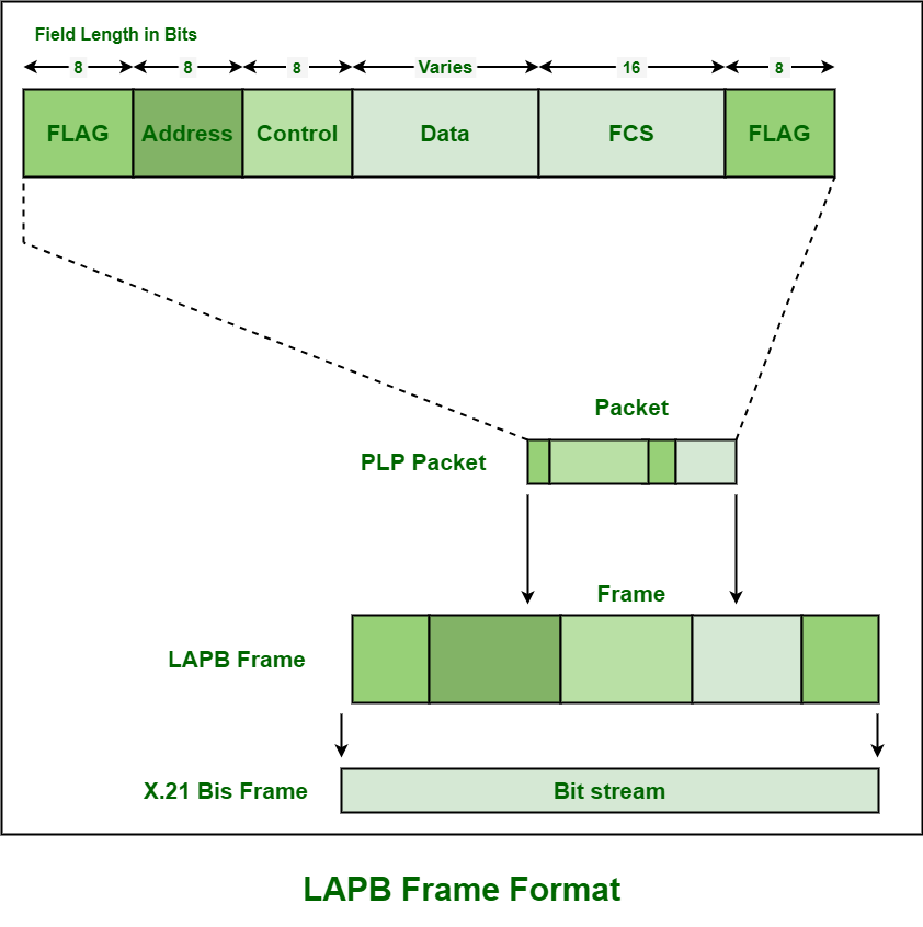
- Flag Field –
Binary Pattern i.e., 01111110 is usually required to mark starting of LAPB frame. Bit stuffing is a technique or mechanism that is used by both of the transmitter and receiver simply to ensure and confirm that this bit pattern of the data frame delimiter flag does not appear or present in the data field of the frame format.
- Address Field –
This field usually contains two types of binary value as given below :
|
Binary Value
|
Transmission
|
| Command |
Response |
| 0000001 |
DTE->DCE |
DCE->DTE |
| 0000011 |
DTE<-DCE |
DCE<-DTE |
Both of these values are not an address. Communication link is full-duplex and either DTE or DCE is usually used to initiate or end communication. This is because communication is in balanced mode.
This field generally has no meaning and usage since protocol works in a point to point mode and even DTE networks are presented in the layer 3 packets. In this, a value of 0*01 simply indicates commands from DTE and also responses from DCE. On the other hand, value of 0*03 indicates commands from DCE and responses from DTE.
- Control Field –
Control field is usually required to represent command and response frames and also to represent and indicate which type of the frame is used i.e., I-frame, S-frame, or U-frame.
In simple words, it is used to determine the type of frame. On the basis of the type of frame, it also contains sequence numbers, various control features, and even error tracking. It basically handles and controls sequence numbers, commands, and responses for controlling flow of data.
- Data field –
This field usually contains data of upper-layer in form of encapsulated PLP Packet. This field varies in size.
- Frame Check Sequence (FCS) –
This field usually controls and handles error checking and also confirms integrity of the data that is being transmitted. It generally enables high-level of physical error control. It is basically used to identify if there is any error occurred during transmission or not.
- End Flag Field –
It is used to indicate represent ending of the frame.
Like Article
Suggest improvement
Share your thoughts in the comments
Please Login to comment...