JK Flip Flop and SR Flip Flop
Last Updated :
06 Jul, 2020
Flip-Flop is popularly known as the basic digital memory circuit. It has two states as logic 1(High) and logic 0(low) states. A flip flop is a sequential circuit which consists of a single binary state of information or data. The digital circuit is a flip flop which has two outputs and are of opposite states. It is also known as a Bistable Multivibrator.
1. JK Flip Flop :
The JK flip flop diagram below represents the basic structure which consists of Clock (CLK), Clear (CLR), and Preset (PR).
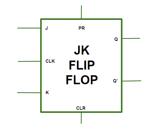
Operations in JK Flip-Flop –
- Case-1:
PR = CLR = 0
This condition is in its invalid state.
- Case-2:
PR = 0 and CLR = 1
The PR is activated which means the output in the Q is set to 1. Therefore, the flip flop is in the set state.
- Case-3:
PR = 1 and CLR = 0
The CLR is activated which means the output in the Q’ is set to 1. Therefore, the flip flop is in the reset state.
- Case-4:
PR = CLR = 1
In this condition, the flip flop works in its normal way whereas the PR and CLR gets deactivated.
JK Flip-Flop with the representation of Preset and Clear –

Truth Table for JK Flip-Flop –

Race Around Condition in JK Flip-Flop –
When the J and K both are set to 1, the input remains high for a longer duration of time, then the output keeps on toggling. Toggle means switching in the output instantly i.e. Q = 0, Q’ = 1 will immediately change to Q = 1 and Q’ = 0 and this continuation keeps on changing. This change in output leads to Race Around Condition.
2. SR Flip-Flop :
In SR flip flop, with the help of Preset and Clear, when the power is switched ON, the state of the circuit keeps on changing, i.e. it is uncertain. It may come to Set (Q = 1) or Reset (Q’ = 0) state. In many applications, it is desired to initially Set or Reset the flip flop. This thing is accomplished by the Preset (PR) and the Clear (CLR).
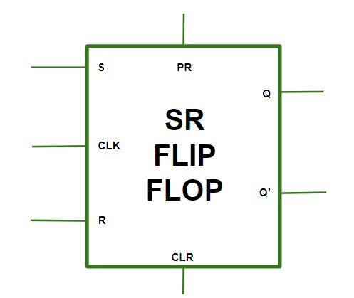
Operations in SR Flip-Flop –
- Case-1:
PR = CLR = 1
The asynchronous inputs are inactive and the flip flop responds freely to the S, R and the CLK inputs in the normal way.
- Case-2:
PR = 0 and CLR = 1
This is used when the Q is set to 1.
- Case-3:
PR = 1 and CLR = 0
This is used when the Q’ is set to 1.
- Case-4:
PR = CLR = 0
This is an invalid state.
SR Flip-Flop with the representation of Preset and Clear –

Truth Table for SR Flip-Flop –

Applications of Flip-Flop :
- Flipflops are used as a bounce elimination switch.
- They are used as a serial to parallel and parallel to serial conversion.
- It is used for counters.
- It is used for frequency divider and also as a latch.
Like Article
Suggest improvement
Share your thoughts in the comments
Please Login to comment...