A clipper in electronics is a circuit created to stop a signal from going over a specific reference voltage level. The remaining portion of the waveform that is applied is not distorted by a clipper. The clipping of a portion of a wave from an input signal is done with Clipper Circuits. A diode is the main component, and it can be used in series or parallel. Clippers have the benefit of removing the unwanted noise that is present in an AC signal’s amplitude.
Types of clippers
The connection and orientation of the diode with the input voltage and the load are used to categorize the different types of clippers. Series clippers, parallel clippers, and double clippers are the three different types of clippers. Positive and negative clippers are additional categories for the series and parallel clippers.
Series clippers:
The diode and output are connected in a series of clipper circuits. In these clippers, when the diode is forward biased and conducting, the input signal is visible at the output.
It is separated into clippers that are positive and negative.
Series Positive clippers:
The positive half of the waveform is removed or clipped with a series of positive clippers. The diode is reverse-biased and connected in series with the output in a series positive clipper, as depicted in the figure below.

Series Positive clipper
Vi is applied as the input signal, and the load resistor receives the output. The voltage at point A is higher than point B during the input’s positive half-cycle. As a result, there is no current conduction and the diode is in reverse bias. There is no voltage drop at the Rl because the input signal cannot pass. As a result, the output does not display the positive half cycle as it does in the figure.
The voltage at point A is lower than that at point B during the negative half-cycle, causing the diode to become forward-biased and the signal to pass through it. The signal is visible throughout the Rl. As a result, the negative half cycle appears at the output after passing through the circuit.
It shows how it clips the positive half of the input waveform and allows the negative half, as shown in the figure.
Series Positive Clippers with Bias: A portion of the half cycle, not the entire halve, is clipped by the biasing in the clippers circuit. To achieve the desired waveforms, a series of positive clippers with either positive or negative biasing is used.
Positive Bias: The positive of the battery is connected to the P side of the diode in a positive clipper circuit like the one below.

Series Positive Clippers with Positive Bias.
The diode is switched off because the voltage at point A is higher than that at point B during the positive half cycle. However, the positive of yet another voltage source is connected to the diode’s P side. The diode is biased forward by the voltage source or battery.
The diode continues to be in forward bias and conducts if the input voltage is lower than the battery voltage. As a result, the output displays the signal. The diode becomes reverse-biased and ceases to transmit the input signal when the input voltage exceeds the battery voltage. As a result, the output displays the battery voltage Vb.
The input and battery voltage causes the diode to be forward biased during the negative half cycle. Consequently, the output signal is produced after the input signal has passed through the diode.
Negative Bias: According to the diagram below, the battery in the negative biased series positive clipper is connected in reverse with the diode.

Series Positive Clippers with Negative Bias.
The negative battery and the input voltage cause the diode to be reversed biased during the positive half cycle. As a result, only the negative battery voltage is displayed at the output during the positive half cycle, when the diode does not conduct.
The diode becomes forward-biased during the negative half-cycle when the polarity of the input voltage is reversed. However, the negative battery causes the diode to be reverse-biased. In this way, the diode possibly becomes forward one-sided in the event that the information voltage increments over the battery voltage and the info signal show up at the result. Otherwise, the output displays a negative voltage from the battery.
Series Negative Clipper:
The negative half of the input cycle is clipped by the series negative clipper circuit. Below is a diagram of its circuitry.

Series Negative Clipper
The input voltage causes the diode to be forward-biased during the positive half cycle. Subsequently, the info signal goes through the diode and shows up in the result.
The diode becomes reverse-biased and does not conduct during the negative half cycle. As a result, the negative half cycle of the input waveform is clipped, and there is no voltage at the output.
Series Negative Clippers with Bias: Instead of clipping the entire negative half, the waveform is modified by biassing the series negative clipper with either a positive or negative voltage battery.
Positive Bias: The voltage of the input signal causes the diode to be forward-biased during the positive half cycle. Nonetheless, the battery voltage causes it to be biased in the opposite direction. The diode’s state is influenced by both voltage sources. As a result, the diode will only conduct when the input voltage exceeds the battery voltage because it will be forward-biased.
series negative clipper with positive bias
The input voltage is initially lower than the battery voltage, causing the diode to be reverse biased and not conduct. As a result, the output shows the battery voltage. When the input signal rises above the battery voltage, as depicted in the figure, the input signal is visible at the output for that portion.
The battery voltage and the input voltage cause the diode to be reversed and biased during the negative half of the cycle. Consequently, during the entire negative half cycle, the output displays only battery voltage.
Negative Bias: The battery voltage and the input signal cause the diode to be forward-biased during the positive half cycle. As a result, the signal flows through the diode for the entire positive half cycle, resulting in the same output as the input.

series negative clipper with negative bias
The input voltage forces the diode into reverse bias during the negative half-cycle, but the battery voltage continues to forward bias the diode. Only when the battery voltage exceeds the input voltage does the diode conduct throughout the entire cycle.
The diode conducts when the input voltage is initially lower than the battery voltage, and the signal appears at the output. However, as depicted in the figure, when it exceeds the battery voltage, the diode blocks the input signal and the battery voltage begins to appear at the output.
Parallel clipper
A parallel clipper is a circuit connection that connects a diode to a load. It also records the positive or negative half-cycle of the input waveform. Parallel clippers come in two varieties: positive parallel clippers and negative parallel clippers.
Parallel positive clipper:
The input waveform’s positive half cycle is clipped by the shunt positive clipper. The shunt-positive clipper’s circuit diagram is shown below.

Parallel positive clipper
The diode is forward-biased during the positive half cycle because the voltage at point A is higher than the voltage at point B. As a result, the diode conducts the input signal and there is no voltage difference at the output.
The voltage polarity of the input signal at points A and B reverses during the negative half-cycle, causing the diode to become reverse biased. As a result, the diode blocks the input signal, and the voltage across the diode is used as the clipper’s output.
In this manner, the positive half of the input cycle is clipped or removed by the shunt-positive clippers, leaving the negative half to run.
Parallel positive clipper with bias: Another fixed voltage source, such as a battery, is used during the biasing process to further alter the waveform. Either positive biasing or negative biasing can be used to connect the voltage source.
Positive bias: The input voltage causes the diode to be forward-biased during the positive half cycle. However, the voltage of the battery causes it to be biased in the opposite direction. The diode’s state will be determined by the sum of the two voltages. The diode will be forward-biased if the input voltage is higher than the battery voltage; otherwise, it will remain reverse-biased.
Parallel positive clipper with positive bias
The diode is reverse biased when the input signal initially falls below the battery voltage, causing the output signal to appear. However, if the voltage rises above that of the battery, the diode begins to conduct the signal and only the battery voltage can be seen at the output.
The diode is reverse biased during the negative half cycle as a result of input voltage and battery voltage. As a result, the output displays the input signal for the entire negative half-cycle.
Negative bias: The diode is forward-biased for both the input signal and the battery voltage during the positive half cycle. As a result, the diode conducts throughout the cycle, displaying only the battery voltage at the output.

Parallel positive clipper with negative bias
The diode is forward biased for battery voltage and reverses biased for input signal during the negative half cycle. The state of the diode is determined by the combined impact of the two voltage sources. When the input voltage is lower than the battery voltage, the diode is forward biased.
The diode is forward-biased because the input signal is lower than the battery voltage at first. As a result, the output displays the battery voltage. The diode becomes reverse-biased when the input voltage exceeds the battery voltage, and as depicted in the figure, the input signal begins to appear at the output.
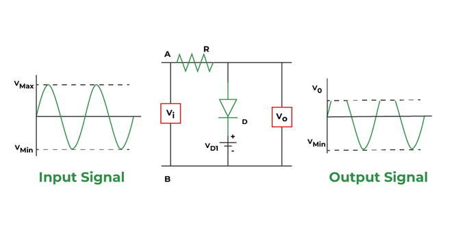
Parallel Negative Clipper:
The negative half of the input waveforms are clipped off using the negative parallel clippers.

Parallel negative clipper
The diode is reverse-biased during the positive half cycle, blocking the signal that crosses it. Consequently, the output also displays the positive half.
The signal is carried by the forward-biased diode during the negative half cycle. For the negative half cycle, there is no voltage at the output. As a result, the negative half of the input waveform is clipped or removed by the shunt negative clipper
Parallel Negative Clipper with Bias: Positive or negative biasing, also known as positive biasing or negative biasing, is used in conjunction with the shunt negative clipper to further alter its waveform. By changing the battery’s voltage, the waveform can be altered.
Positive bias: The diode is biased forward for battery voltage but reversed for input voltage during the positive half cycle. Therefore, the only time the input voltage exceeds the battery voltage will cause the diode to be reversely biased, at which point the input signal will be output.

Parallel negative clipper with positive Bias
The diode is forward biased and conducts the signal when the signal is initially lower than the battery’s capacity. As a result, the output only displays the battery voltage. however, the diode becomes reverse biased and the signal appears at the output as shown in the figure when the input signal is greater than the battery voltage.
The diode is forward biased for both the input signal and the battery voltage during the negative half cycle. The diode conducts as a result, and only the battery voltage is visible at the output throughout the entire negative cycle.
Negative bias: The diode is reverse-biased for both input voltage and battery voltage during the positive half cycle. As a result, the voltage is blocked by the diode, and the signal remains at the output throughout the entire positive half cycle.

Parallel negative clipper with negative Bias
When the input voltage is higher than the battery voltage during the negative half cycle, the diode conducts. As a result, the diode blocks and the signal is output when the voltage is lower than the battery voltage. Only the battery voltage is visible at the output when the input voltage exceeds; the diode then begins to conduct.
Dual clipper:
The two diodes and the load resistor are parallel to one another in the double clipper, which is a combination clipper. When a portion of both the positive and negative input cycle needs to be cut off, this technique is used.
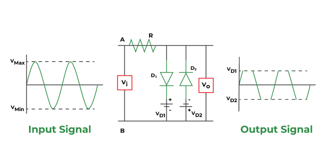
Dual Clipper
The circuit works on a straightforward principle. The input signal would be visible across the diode and also at the output if both diodes were reverse biased or if they did not conduct. Now, if one of the diodes begins to conduct, the output will start to show the voltage of the corresponding battery.
The diode D1 is forward biased for input voltage during the positive half cycle, while the diode D2 is reverse biased. But for the battery voltages VB1 and VB2, respectively, the diode D1 and D2 are reverse biased.
The diode D1 is biased forward for the input voltage and reversed for the battery voltage VB1 during the positive half cycle. While the diode D2 is biased in the opposite direction for both the battery voltage VB2 and the input voltage,
The diode D1 is initially biased in the opposite direction because the input voltage is lower than the battery voltage VB1.while the diode D2 is already biased in the wrong direction. Consequently, the output displays the input signal. Diode D1 begins to conduct when the input voltage exceeds VB1, and battery voltage VB1 begins to appear at the output
Due to input voltage and battery voltage VB1, the diode D1 is reverse biased during the negative half cycle. Due to input voltage, the diode D2 is forward biased; however, battery voltage VB2 causes it to be reverse biased.
The diode D2 is initially biased in the reverse direction and does not conduct because the input voltage is lower than VB2. Reverse bias is already present in diode D1. As a result, the output signal is the input signal. The battery voltage VB2 manifests itself at the output when the input voltage exceeds VB2, at which point the diode begins to conduct.
Application of Clipper:
- The clipper circuit limits voltage in power supplies because it provides overvoltage protection.
- For the separation of synchronizing signals from composite picture signals, clippers are frequently used.
- An ac signal’s amplitude contains unwanted noise, which clippers remove.
- They are utilized in television transmitters and receivers.
- They are used to create new waveforms like squares, triangles, and others, or to modify existing waveforms.
Like Article
Suggest improvement
Share your thoughts in the comments
Please Login to comment...