Interactive Graphical Techniques in Computer Graphics
Last Updated :
10 Aug, 2020
To construct various images and graphics in interactive manner, there are different methods which are built into various graphics packages. These packages contains various options which help user to enter information of coordinate by using stroke devices or various locators. These coordinates helps in creating boundaries for various objects which user is going to drawn.
Positioning Techniques :
- It very basic technique of graphical input. It is also known as locating.
- With the help of input device, user indicates position on the screen. To display object this position marks location. Example: input position can be used to insert symbol to specify endpoint of line.
- The process of positioning involves two steps, in first step user have to move cursor to desired spot on screen and in second step user inform computer by pressing key or button.
- The positioning is very often used in geometric modeling applications, where if user wants to define new element of model or to change position of already existing model.
Positioning Constraints :
Constraint is rule which is used by user to change value of coordinates to produce required alignment of displayed coordinates. There are 3 types of positioning constraints which are as follows :
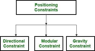
Figure – Types of Constraints
- Directional constraint –
Directional constraint is used to straight line segment. It is basically used to create horizontal and vertical lines; without thinking about endpoint coordinates. The user specifies two endpoints. Usually program specify line drawn by user is more nearly horizontal or vertical and draws line parallel to axis which he wants to draw. The distance between two input points is length of line.

Figure – Directional Constraint
- Modular constraint –
This constraint uses grid of rectangular areas which is displayed o screen. Any input coordinate position is to be present on nearest intersection of two grid lines. This constraint is applicable to symbols as well as line endpoints.

Figure – Modular Constraint
In the above figure, it is shown that there is usage of grid lines to draw line. Cursor is shifted to nearest grid intersection point and user draw line between these grid points.
- Gravity Field –
This constraint is useful where there is need to attach line or line in already existing picture. In this, picture does not lie on grid system. The name of this constraint is so because there is gravitational pull in between lines on screen.
In this constraint, input position which is near line is converted to input position on line. In this, there is invisible area around each of line which has shape like of dumbbell or sausage which is as shown in the following figure:

Gravity fields size is chosen not very large enough to aid positioning but small to reduce chances of overlapping with other lines.
Rubber Band Method :
This method is used to construct and position straight line segments. This method stretch line from starting position as movement of screen cursor. The user first selects position from one endpoint of line and then it moves cursor around, hen line is displayed from where user start cursor and position where cursor is placed now. Finally when user selects second endpoint on screen, then final line is displayed from starting endpoint to second endpoint on screen.
The name is Elastic or Rubber Band Technique because of effect of elastic line which is stretched between first endpoint and cursor.
In this method user will get idea about line which user is drawing before actually fixing that line.
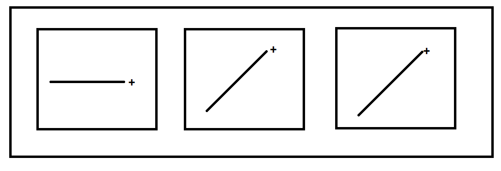
Figure – Rubber band line
This method is also used to draw other geometric entities like arc and rectangles. The rectangle using this method is shown in the following figure:
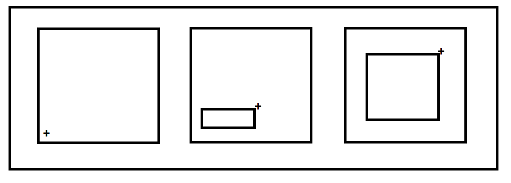
Figure – Rectangle using rubber band technique
Inking :
It is other technique used to create geometric patterns.
In this method locator itself leaves trail of line segment as way pen leaves trail of ink.
There is no need of pushing button for every line segment in required picture. In this method automatically new line is drawn when locator move towards sufficient distance which is as shown in the following figure:
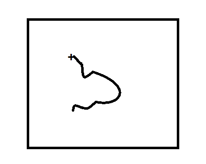
Figure – Inking
Like Article
Suggest improvement
Share your thoughts in the comments
Please Login to comment...