DATA processing instructions :
We use data processing instructions to manipulate data within the registers.
Types for data processing instructions –
- Arithmetic instructions
- Logical instructions
- Multiply instructions
- Comparison instructions
- Move instructions
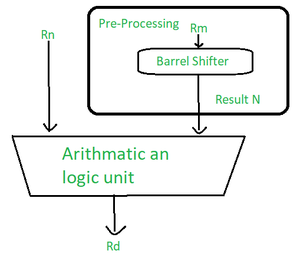
Most of the data processing instructions use a barrel shifter to pre-process the data of one of their operands. Each operation updates different flags in the cpsr (To learn more about ‘CPSR’ search “CPSR in ARM”).
Let us discuss the instructions in detail.
1. Arithmetic instructions :
The arithmetic instructions mainly implement addition and subtraction of 32bit signed and unsigned values.
Syntax: <instruction>{<cond>}{s} Rd, Rn, N
| ADC |
add with 32-bit values and carry |
Rd=Rn+N+carry |
| ADD |
add two 32-bit values |
Rd=Rn+N |
| RSB |
reverse subtract of two 32-bit values |
Rd=N-Rn |
| RSC |
reverse subtract with carry of two 32-bit values |
Rd=N-Rn-!(Carry flag) |
| SBC |
subtract with carry of two 32-bit values |
Rd=Rn-N-!(Carry flag) |
| SUB |
subtract two 322-bit values |
Rd=Rn-N |
| N is the result of the shift operation. |
Examples –
1. This simple subtract instruction subtracts a value stored in register r2 from a value stored in register r1. The result is stored in register r0
PRE
r0 = 0x00000000 ; As this register is a register to hold the output, that’s why it is empty before execution
r1 = 0x000000002 ; register r1 holds the value ‘2’
r2 = 0x000000001 ; r2 holds another value ‘1’
SUB r0, r1, r2 ; r0=r1 – r2. Here the subtracted value (r0 – r1) is moved to r0 after performing operation.
POST
r0 = 0x00000001 ; This is the output of above instruction moved to r0 register
2. This reverse subtract instruction (RSB) subtracts r1 from the constant value #0, writing the result to r0.
Reverse subtraction is helpful for integer values so that the instruction can be subtracted with no complexity.
PRE
r0 = 0x00000000 ; Output register
r1= 0x00000077 ; value to be reverse subtracted
RSB r0, r1, #0 ; Rd = 0x- – r1
POST
r0 = -r1 = 0xffffff89 ; reversed output gets generated and stored in the register r0
Usage of barrel shifter with arithmetic instructions –
Barrel shifting is one of the powerful features of the ARM instruction set.
It pre processes one of the operand/ registers before performing operation on it.
Example –
PRE
r0 = 0x00000000
r1 = 0x00000005
ADD r0, r1, r1, LSL #1
POST
r0 = 0x0000000f
r1 = 0x00000005
2. Logical Instruction –
Logical instructions perform bitwise logical operations on the two source registers.
Syntax: <instruction>{<cond>} {S} Rd, Rn, N
| AND |
logical bitwise AND of two 32-bit values |
Rd = Rn & N |
| ORR |
logical bitwise OR of two 32-bit values |
Rd = Rn | N |
| EOR |
logical exclusive OR of two 32-bit values |
Rd = Rn ^ N |
| BIC |
logical bit clear (AND NOT) |
Rd = Rn &~ N |
Example –
1. This example shows a logical OR operation between registers r1 and r2, r0 holds the result.
PRE
r0 = 0x00000000
r1 = 0x02040608
r2 = 0x10305070
ORR r0, r1, r2
POST
r0 = 0x12345678
2. This example shows a more complicated logical instruction called BIC, which carries out a logical bit clear.
PRE
r1 = 0b1111
r2 = 0b0101
BIC r0, r1, r2
POST
r0 = 0b1010
3. Multiply Instruction –
The multiply instructions multiply the contents of a pair of registers depending upon the instruction, and accumulate the result along with another register . The long multiplies accumulate onto a pair of registers representing a 64-bit value. The final result is placed on a destination register or pair of registers.
Syntax – MLA{<cond>}{S} Rd, Rm, Rs, Rn
MUL{<cond>}{S} Rd, Rm, Rs
| MLA |
Multiply and accumulate |
Rd = (Rm * Rs) + Rn |
| MUL |
multiply |
Rd = Rm * Rs |
Syntax – <instruction>{<cond>}{S} RdLo, RdHi, Rm, Rs
| SMLAL |
signed multiply accumulate long |
[RdHi, RdLo] = [RdHi, RdLo] + (Rm * Rs) |
| SMULL |
signed multiply long |
[RdHi, RdLo] = Rm * Rs |
| UMLAL |
unsigned multiply accumulate long |
[RdHi, RdLo] = [RdHi, RdLo] + (Rm * Rs) |
| UMULL |
unsigned multiply long |
[RdHi, RdLo] = Rm * Rs |
Processor implementation handles the number of cycles taken to execute a multiply instruction.
Example 1 –
- This example represents the simple multiply instruction that multiplies registers r1 and r2 together and places the result into a register r0.
- Register r1 is equal to the value 2, and r2 is equal to 2, then replaced to r0.
PRE
r0 = 0x00000000 ; register to hold the output
r1 = 0x00000002 ; register holding the operand 1 value
r2 = 0x00000002 ; register holding the operand 2 value
MUL r0, r1, r2 ; r0 = r1 * r2
POST
r0 = 0x00000004 ; output of the multiplication operation
r1 = 0x00000002
r2 = 0x00000002 ; operands
Example 2 –
PRE
r0 = 0x00000000
r1 = 0x00000000
r2 = 0xf0000002
r3 = 0x00000002
UMULL r0, r1, r2, r3 ; [r1, r0] = r2 * r3
POST
r0 = 0xe0000004 ; = RdLo
r1 = 0x00000001 ; = RdHi
4. Comparison Instructions –
These instructions are used to compare or test a register with a 32-bit value. They update the cpsr flag bits according to the result, but do not affect other registers. After the bits have been set, the information can then be used to change program flow by using conditional execution.
Syntax – <instruction>{<cond>} Rn, N
| CMN |
compare negated |
flags set as a result of Rn + N |
| CMP |
compare |
flags set as a result of Rn – N |
| TEQ |
test for quality of two 32 – bit values |
flags set as a result of Rn ^ N |
| TST |
test bits of a 32-bit value |
flags set as a result of Rn & N |
| N is the result of the shifter operation. |
Example –
PRE
cpsr = nzcvqift_USER
r0 = 4 ; register to be compared
r9 = 4 ; register to be compared
CMP r0, r9
POST
cpsr = nzcvqift_USER output generated after comparison
5. Move Instructions –
Move is the simplest ARM instruction. It copies N into a destination register Rd, where N is a register or immediate value. This instruction is useful for setting initial values and transferring data between registers.
Syntax – <instruction>{<cond>}{S} Rd, N
| MOV |
Move a 32-bit value into a register |
Rd = N |
| MVN |
move the NOT of the 32-bit value into a register |
Rd = ~N |
Example –
PRE
r5 = 5 ; register value
r7 = 8 ; register value
MOV r7, r5 ;let r7 = r5
POST
r5 = 5 ; data in the register after moving the r5 data into r7
r7 = 5 ; output after move operation
Barrel Shifter –
It is a device to shift a word with variable amount. It is one of the logic devices used to pre-process one of the operand/register before operating on to the ALU operations. And it is one of the best features of ARM.
Barrel Shifter
| Mnemonics |
Description |
Shift |
Result |
Shift amount |
| LSL |
logical shift left |
xLSLy |
x<<y |
#0-31 or Rs |
| LSR |
logical shift right |
xLSRy |
(unsigned) x>>y |
#1-32 or Rs |
| ASR |
arithmetic right shift |
xASRy |
(signed) x>>y |
#1-32 or Rs |
| ROR |
rotate right |
xRORy |
((unsigned) x>>y) | (x<<(32 – y) |
#1-31 or Rs |
| RRX |
rotate right extended |
xRRX |
(c flag << 31) | ((unsigned) x>>1) |
none |
| x represents the register being shifted and y represent the shift amount |
| N shift operations |
Syntax |
| Immediate |
#immediate |
| Register |
Rm |
| Logical shift left by immediate |
Rm, LSL #shift_imm |
| Logical shift left by register |
Rm, LSL Rs |
| Logical shift right by immediate |
Rm, LSR #shift_imm |
| Logical shift right by register |
Rm, LSR Rs |
| Arithmetic shift right by immediate |
Rm, ASR #shift_imm |
| Arithmetic shift right by register |
Rm, ASR Rs |
| Rotate right by immediate |
Rm, ROR #shift_imm |
| Rotate right by register |
Rm, ROR Rs |
| rotate right with extend |
Rm, RRX |
Example –
- This example of a MOVS instruction shifts register r1 left by one bit.
- This multiplies register r1 by a value 21
PRE
cpsr = nzcvqiFt_USER
r0 = 0x00000000
r1 = 0x80000004
MOVS r0, r1, LSL #1
POST
cpsr = nzCvqiFt_USER
r0 = 0x00000008
r1 = 0x80000004
- The C flag is updated in the CPSR because the S suffix is present in the instruction mnemonics.
Like Article
Suggest improvement
Share your thoughts in the comments
Please Login to comment...