An encoder is a digital circuit that converts a set of binary inputs into a unique binary code. The binary code represents the position of the input and is used to identify the specific input that is active. Encoders are commonly used in digital systems to convert a parallel set of inputs into a serial code.
The basic principle of an encoder is to assign a unique binary code to each possible input. For example, a 2-to-4 line encoder has 2 input lines and 4 output lines and assigns a unique 4-bit binary code to each of the 2^2 = 4 possible input combinations. The output of an encoder is usually active low, meaning that only one output is active (low) at any given time, and the remaining outputs are inactive (high). The active low output is selected based on the binary code assigned to the active input.
There are different types of encoders, including priority encoders, which assign a priority to each input, and binary-weighted encoders, which use a binary weighting system to assign binary codes to inputs. In summary, an encoder is a digital circuit that converts a set of binary inputs into a unique binary code that represents the position of the input. Encoders are widely used in digital systems to convert parallel inputs into serial codes.
An Encoder is a combinational circuit that performs the reverse operation of a Decoder. It has a maximum of 2^n input lines and ‘n’ output lines, hence it encodes the information from 2^n inputs into an n-bit code. It will produce a binary code equivalent to the input, which is active High. Therefore, the encoder encodes 2^n input lines with ‘n’ bits.
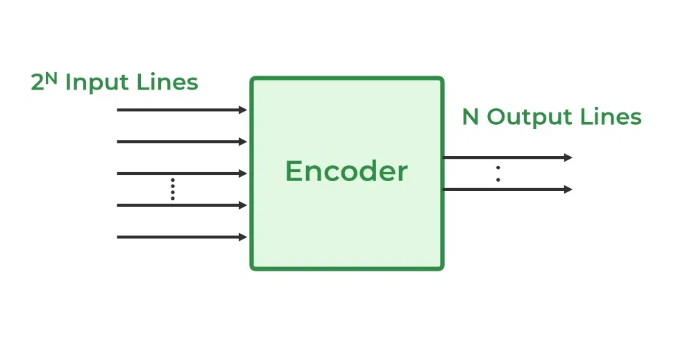
Encoder
Types of Encoders
There are different types of Encoders which are mentioned below.
- 4 to 2 Encoder
- Octal to Binary Encoder (8 to 3 Encoder)
- Decimal to BCD Encoder
- Priority Encoder
4 to 2 Encoder
The 4 to 2 Encoder consists of four inputs Y3, Y2, Y1 & Y0, and two outputs A1 & A0. At any time, only one of these 4 inputs can be ‘1’ in order to get the respective binary code at the output. The figure below shows the logic symbol of the 4 to 2 encoder.
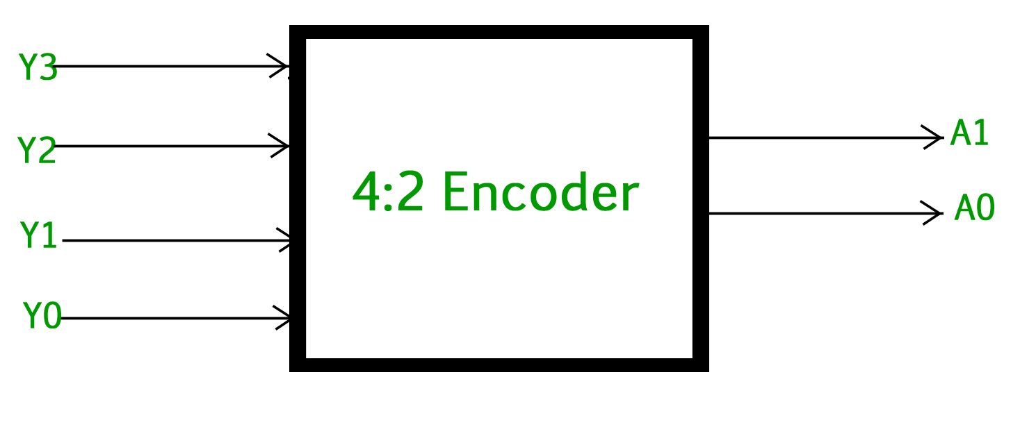
4 to 2 Encoder
The Truth table of 4 to 2 encoders is as follows.
| INPUTS |
OUTPUTS |
| Y3 |
Y2 |
Y1 |
Y0 |
A1 |
A0 |
| 0 |
0 |
0 |
1 |
0 |
0 |
| 0 |
0 |
1 |
0 |
0 |
1 |
| 0 |
1 |
0 |
0 |
1 |
0 |
| 1 |
0 |
0 |
0 |
1 |
1 |
Logical expression for A1 and A0:
A1 = Y3 + Y2
A0 = Y3 + Y1
The above two Boolean functions A1 and A0 can be implemented using two input OR gates :
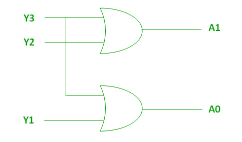
Implementation using OR Gate
Octal to Binary Encoder (8 to 3 Encoder)
The 8 to 3 Encoder or octal to Binary encoder consists of 8 inputs: Y7 to Y0 and 3 outputs: A2, A1 & A0. Each input line corresponds to each octal digit and three outputs generate corresponding binary code. The figure below shows the logic symbol of octal to the binary encoder.
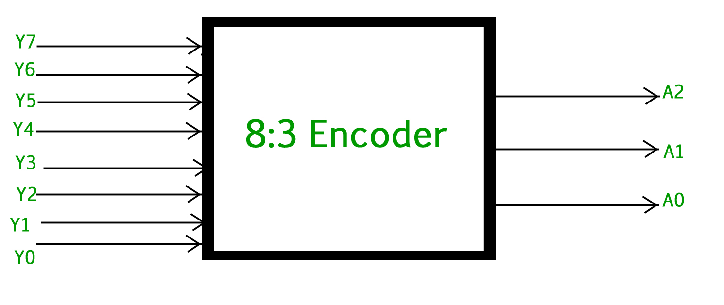
Octal to Binary Encoder (8 to 3 Encoder)
The truth table for the 8 to 3 encoder is as follows.
| INPUTS |
OUTPUTS |
| Y7 |
Y6 |
Y5 |
Y4 |
Y3 |
Y2 |
Y1 |
Y0 |
A2 |
A1 |
A0 |
| 0 |
0 |
0 |
0 |
0 |
0 |
0 |
1 |
0 |
0 |
0 |
| 0 |
0 |
0 |
0 |
0 |
0 |
1 |
0 |
0 |
0 |
1 |
| 0 |
0 |
0 |
0 |
0 |
1 |
0 |
0 |
0 |
1 |
0 |
| 0 |
0 |
0 |
0 |
1 |
0 |
0 |
0 |
0 |
1 |
1 |
| 0 |
0 |
0 |
1 |
0 |
0 |
0 |
0 |
1 |
0 |
0 |
| 0 |
0 |
1 |
0 |
0 |
0 |
0 |
0 |
1 |
0 |
1 |
| 0 |
1 |
0 |
0 |
0 |
0 |
0 |
0 |
1 |
1 |
0 |
| 1 |
0 |
0 |
0 |
0 |
0 |
0 |
0 |
1 |
1 |
1 |
Logical expression for A2, A1, and A0.
A2 = Y7 + Y6 + Y5 + Y4
A1 = Y7 + Y6 + Y3 + Y2
A0 = Y7 + Y5 + Y3 + Y1
The above two Boolean functions A2, A1, and A0 can be implemented using four input OR gates.
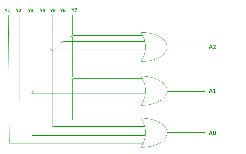
Implementation using OR Gate
Decimal to BCD Encoder
The decimal-to-binary encoder usually consists of 10 input lines and 4 output lines. Each input line corresponds to each decimal digit and 4 outputs correspond to the BCD code. This encoder accepts the decoded decimal data as an input and encodes it to the BCD output which is available on the output lines. The figure below shows the logic symbol of the decimal to BCD encoder :
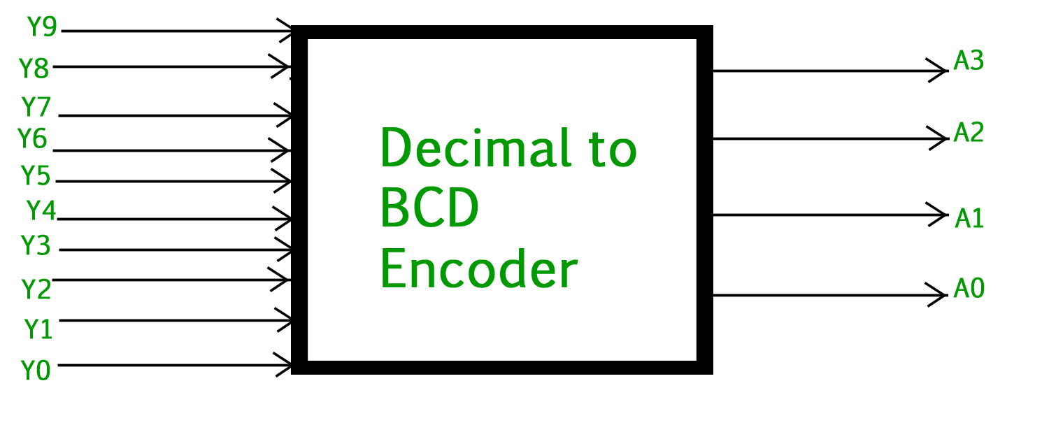
Decimal to BCD Encoder
The truth table for decimal to BCD encoder is as follows.
| INPUTS |
OUTPUTS |
| Y9 |
Y8 |
Y7 |
Y6 |
Y5 |
Y4 |
Y3 |
Y2 |
Y1 |
Y0 |
A3 |
A2 |
A1 |
A0 |
| 0 |
0 |
0 |
0 |
0 |
0 |
0 |
0 |
0 |
1 |
0 |
0 |
0 |
0 |
| 0 |
0 |
0 |
0 |
0 |
0 |
0 |
0 |
1 |
0 |
0 |
0 |
0 |
1 |
| 0 |
0 |
0 |
0 |
0 |
0 |
0 |
1 |
0 |
0 |
0 |
0 |
1 |
0 |
| 0 |
0 |
0 |
0 |
0 |
0 |
1 |
0 |
0 |
0 |
0 |
0 |
1 |
1 |
| 0 |
0 |
0 |
0 |
0 |
1 |
0 |
0 |
0 |
0 |
0 |
1 |
0 |
0 |
| 0 |
0 |
0 |
0 |
1 |
0 |
0 |
0 |
0 |
0 |
0 |
1 |
0 |
1 |
| 0 |
0 |
0 |
1 |
0 |
0 |
0 |
0 |
0 |
0 |
0 |
1 |
1 |
0 |
| 0 |
0 |
1 |
0 |
0 |
0 |
0 |
0 |
0 |
0 |
0 |
1 |
1 |
1 |
| 0 |
1 |
0 |
0 |
0 |
0 |
0 |
0 |
0 |
0 |
1 |
0 |
0 |
0 |
| 1 |
0 |
0 |
0 |
0 |
0 |
0 |
0 |
0 |
0 |
1 |
0 |
0 |
1 |
Logical expression for A3, A2, A1, and A0.
 A3 = Y9 + Y8
 A2 = Y7 + Y6 + Y5 +Y4
 A1 = Y7 + Y6 + Y3 +Y2
 A0 = Y9 + Y7 +Y5 +Y3 + Y1
The above two Boolean functions can be implemented using OR gates.
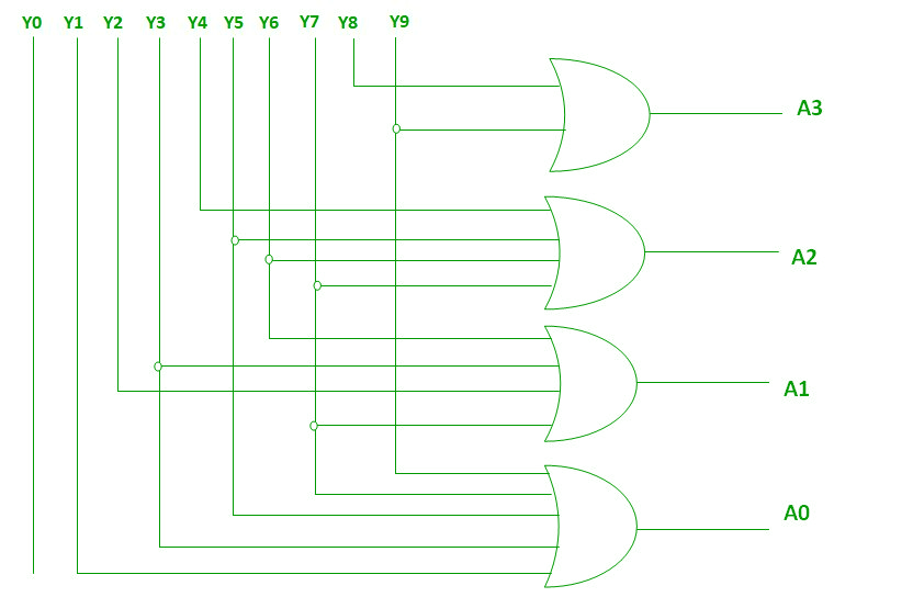
Implementation using OR Gate
Priority Encoder
A 4 to 2 priority encoder has 4 inputs: Y3, Y2, Y1 & Y0, and 2 outputs: A1 & A0. Here, the input, Y3 has the highest priority, whereas the input, Y0 has the lowest priority. In this case, even if more than one input is ‘1’ at the same time, the output will be the (binary) code corresponding to the input, which is having higher priority. The truth table for the priority encoder is as follows.
| INPUTS |
OUTPUTS |
| Y3 |
Y2 |
Y1 |
Y0 |
A1 |
A0 |
V |
| 0 |
0 |
0 |
0 |
X |
X |
0 |
| 0 |
0 |
0 |
1 |
0 |
0 |
1 |
| 0 |
0 |
1 |
X |
0 |
1 |
1 |
| 0 |
1 |
X |
X |
1 |
0 |
1 |
| 1 |
X |
X |
X |
1 |
1 |
1 |
The logical expression for A1 is shown below.
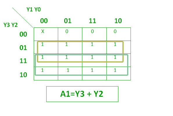
Logical Expression
The Logical Expression for A0 is shown below.
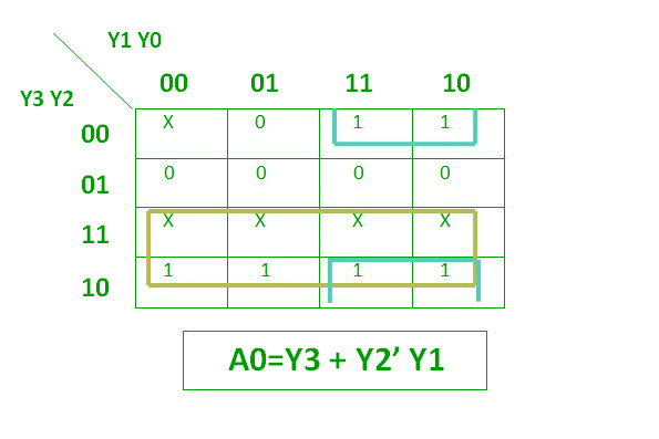
Logical Expression
The above two Boolean functions can be implemented as.
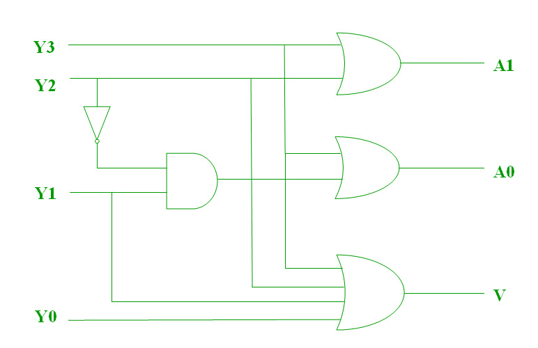
Priority Encoder
There are some errors that usually happen in Encoders are mentioned below.
- There is an ambiguity, when all outputs of the encoder are equal to zero.
- If more than one input is active High, then the encoder produces an output, which may not be the correct code.
So, to overcome these difficulties, we should assign priorities to each input of the encoder. Then, the output of the encoder will be the code corresponding to the active high inputs, which have higher priority.
Application of Encoders
- Encoders are very common electronic circuits used in all digital systems.
- Encoders are used to translate the decimal values to the binary in order to perform binary functions such as addition, subtraction, multiplication, etc.
- Other applications especially for Priority Encoders may include detecting interrupts in microprocessor applications.
Advantages of Using Encoders in Digital Logic
- Reduction in the number of lines: Encoders reduce the number of lines required to transmit information from multiple inputs to a single output, which can simplify the design of the system and reduce the cost of components.
- Improved reliability: By converting multiple inputs into a single serial code, encoders can reduce the possibility of errors in the transmission of information.
- Improved performance: Encoders can enhance the performance of a digital system by reducing the amount of time required to transmit information from multiple inputs to a single output.
Disadvantages of Using Encoders in Digital Logic
- Increased complexity: Encoders are typically more complex circuits compared to multiplexers, and require additional components to implement.
- Limited to specific applications: Encoders are only suitable for applications where a parallel set of inputs must be converted into a serial code.
- Limited flexibility: Encoders are limited in their flexibility, as they can only encode a fixed number of inputs into a fixed number of outputs.
- In conclusion, Encoders are useful digital circuits that have their advantages and disadvantages. The choice of whether to use an encoder or not depends on the specific requirements of the system and the trade-offs between complexity, reliability, performance, and cost.
GATE CS Corner Questions
Practicing the following questions will help you test your knowledge. All questions have been asked in GATE in previous years or in GATE Mock Tests. It is highly recommended that you practice them.
- GATE CS 2013, Question 65
- GATE CS 2014 (Set 3), Question 65
Share your thoughts in the comments
Please Login to comment...