Difference Between AND Gate and OR Gate
Last Updated :
16 Jun, 2022
A logic gate is a simple switching circuit that determines whether an input pulse can pass through to the output in digital circuits.
The building blocks of a digital circuit are logic gates, which execute numerous logical operations that are required by any digital circuit. These can take two or more inputs but produce only one output.
The mix of inputs applied across a logic gate determines its output. Logic gates use Boolean algebra to execute logical processes. Logic gates are found in nearly every digital gadget we use on a regular basis. Logic gates are used in the architecture of our telephones, laptops, tablets, and memory devices.
AND Gate:
A logic gate that is defined to execute the logical multiplication of binary input is known as the AND Gate. The AND operation is performed the same as ordinary multiplications of 1s and 0s. An AND gate is a logic circuit that performs the AND operations on the circuit’s input. The AND Gate gives output 1 when all the inputs are 1, for all other cases output will be 0. A dot(.) is show the AND operation. The AND Gate is an electronic circuit that gives a high output(1) only if all its inputs are high. AND Gate is one of the Basic Gates.
The expression x = A.B is read as “x equals to the A AND B.”
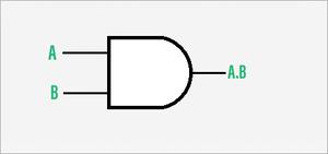
Symbol of AND Gate
Truth Table of AND Gate:
For n=2 (where n is the number of inputs).
| INPUTS |
OUTPUT |
|
A
|
B
|
A.B
|
| 1 |
1 |
1 |
| 1 |
0 |
0 |
| 0 |
1 |
0 |
| 0 |
0 |
0 |
Applications
Real-life application of AND Gate:
- Data transfer.
- Push Button.
OR Gate:
A logic gate that is defined to execute the logical addition of binary input is known as the OR Gate. The OR Gate gives output 1 when either input is 1, otherwise, the output is 0. A plus(+) is show the OR operation The OR Gate is an electronic circuit that gives an output(1) if one or more of its input is high. OR Gate is one of the Basic Gates. An OR Gate performs like two switches in parallel supplying a light so that when either one of the switches is closed the light is on.
The expression x = A+B is read as “x equals to the A OR B.”
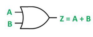
Symbol of OR Gate
Truth table of OR Gate:
For n=2 (where n is the number of inputs).
| INPUTS |
OUTPUT |
| A |
B |
Z = A +B |
| 1 |
1 |
1 |
| 1 |
0 |
1 |
| 0 |
1 |
1 |
| 0 |
0 |
0 |
Applications:
Real-life application of OR Gate:
- Detection of excess temperature.
- Detection of excess pressure.
Difference between AND Gate and OR Gate:
| S.NO. |
Parameter |
AND Gate |
OR Gate |
| 1. |
Executes |
AND Gate executes logical multiplication. |
OR Gate executes logical addition. |
| 2. |
Implements |
AND Gate implements logical conjunction. |
OR Gate implements logical disjunction. |
| 3. |
Represent |
AND Gate is represented by a dot(.)
Example :- Z = A.B
|
OR Gate is represented by a plus(+).
Example :- Z = A+B
|
| 4. |
True Output |
AND Gate gives true output only when both inputs are true. |
OR Gate gives a true output when at least one output is true. |
| 5. |
High output |
The AND Gate gives high output only if all its inputs are high |
The OR Gate gives output if one or more of its inputs is high. |
Like Article
Suggest improvement
Share your thoughts in the comments
Please Login to comment...