Design counter for given sequence
Last Updated :
22 Feb, 2023
Prerequisite – Counters Problem – Design synchronous counter for sequence: 0 → 1 → 3 → 4 → 5 → 7 → 0, using T flip-flop. Explanation – For given sequence, state transition diagram as following below: 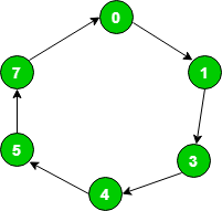 State transition table logic:
| Present State |
Next State |
| 0 |
1 |
| 1 |
3 |
| 3 |
4 |
| 4 |
5 |
| 5 |
7 |
| 7 |
0 |
State transition table for given sequence:
| Present State |
Next State |
| Q3 |
Q2 |
Q1 |
Q3(t+1) |
Q2(t+1) |
Q1(t+1) |
| 0 |
0 |
0 |
0 |
0 |
1 |
| 0 |
0 |
1 |
0 |
1 |
1 |
| 0 |
1 |
1 |
1 |
0 |
0 |
| 1 |
0 |
0 |
1 |
0 |
1 |
| 1 |
0 |
1 |
1 |
1 |
1 |
| 1 |
1 |
1 |
0 |
0 |
0 |
T flip-flop – If value of Q changes either from 0 to 1 or from 1 to 0 then input for T flip-flop is 1 else input value is 0.
| Qt |
Qt+1 |
T |
| 0 |
0 |
0 |
| 0 |
1 |
1 |
| 1 |
0 |
1 |
| 1 |
1 |
0 |
Draw input table of all T flip-flops by using the excitation table of T flip-flop. As nature of T flip-flop is toggle in nature. Here, Q3 as Most significant bit and Q1 as least significant bit.
| Input table of Flip-Flops |
| T3 |
T2 |
T1 |
|
| 0 |
0 |
1 |
|
| 0 |
1 |
0 |
|
| 1 |
1 |
1 |
|
| 0 |
0 |
1 |
|
| 0 |
1 |
0 |
|
| 1 |
1 |
1 |
|
Find value of T3, T2, T1 in terms of Q3, Q2, Q1 using K-Map (Karnaugh Map): 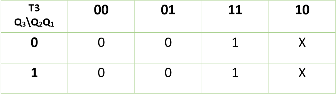 Therefore,
T3 = Q2
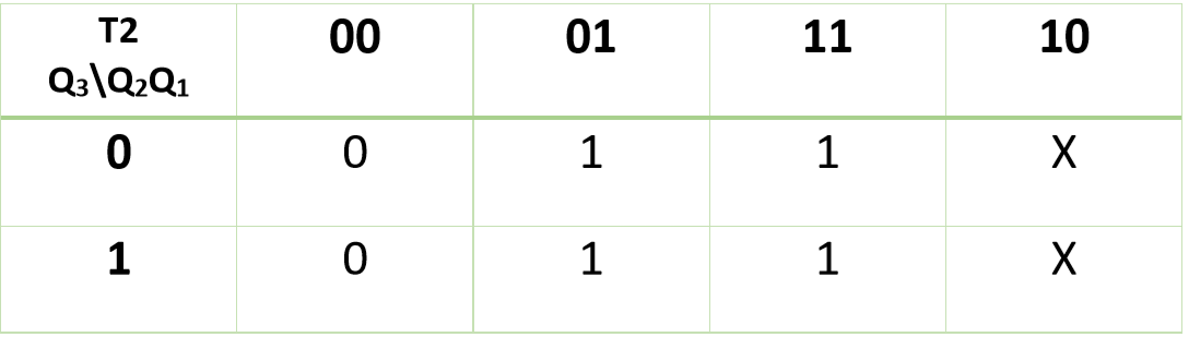 Therefore,
T2 = Q1
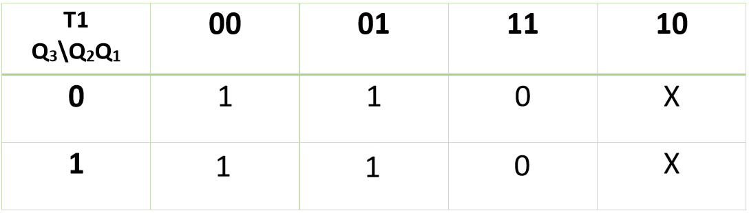 Therefore,
T1 = Q2+Q1'
Now, you can design required circuit using expressions of K-maps: 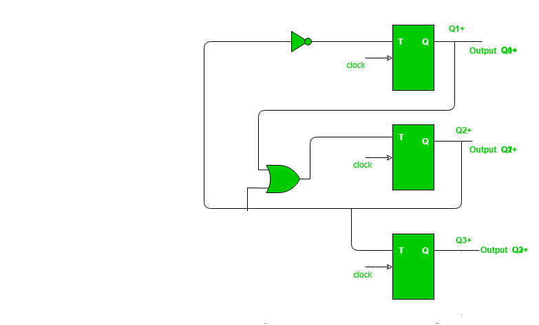
Like Article
Suggest improvement
Share your thoughts in the comments
Please Login to comment...