Control Signals in 8155 Microprocessor
Last Updated :
03 Mar, 2020
In handshake mode, when both the ports A and B are configured, port A uses the lower three signals of port C(i.e, PC0, PC1, PC2) and port B uses the upper three signals (i.e, PC3, PC4, PC5).
The diagram can be followed as:
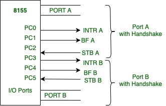
Figure – 8155 with Handshake mode
The functions of the above signals can be seen as follows:
- STB (Strobe Input):
This is an input handshake signal. This is connected from a peripheral to the 8155. The low on this signal informs the 8155 that data are strobed into the input port.
- BF (Buffer Full):
This is an active high signal, which basically indicates the presence of a data byte in the port.
- INTR (Interrupt Request):
As clear from the name itself, the rising edge of the STB signal generates this signal. This happens whenever the interrupt flip-flop (INTE) is enabled. This can be used to interrupt the MPU.
- INTE (Interrupt Enable):
This is an internal flip-flop which is used to enable or disable the interrupt capability of the 8155. The interrupts of port A and port B are controlled by bits D4 and D5, respectively, in the control register.
These control signals can be used to implement either interrupt I/O or status check I/O.
Share your thoughts in the comments
Please Login to comment...