Common Bus System using multiplexers
Last Updated :
20 May, 2020
A typical computer has many registers and we need to transfer the information between these registers. A way to transfer the information is using the common bus system. In this article we shall discuss the common bus system using multiplexers.
Let’s discuss the common bus system with multiplexers.
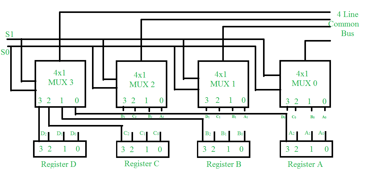
The construction of this bus system for 4 registers is shown above. The bus consists of 4×1 multiplexers with 4 inputs and 1 output and 4 registers with bits numbered 0 to 3. There are 2 select inputs S0 and S1 which are connected to the select inputs of the multiplexers.
The output 1 of register A is connected to input 0 of MUX 1 and similarly other connections are made as shown in the diagram. The data transferred to the bus depends upon the select lines. A table for the various combinations of select lines is shown below.
| Select Lines combination S1S0 |
Register Selected |
| 00 |
Register A |
| 01 |
Register B |
| 10 |
Register C |
| 11 |
Register D |
As we can see that when S1S0=00, register A is selected because on 00 the 0 data inputs of all the multiplexers are applied to the common bus.
Since the 0 data inputs of all the multiplexers receive the inputs from the register A, thus register A gets selected. Similarly for other combinations of S1S0 other register are selected.
Note-
No. of multiplexers needed = No. of bits in each register
Like Article
Suggest improvement
Share your thoughts in the comments
Please Login to comment...