Command words of 8259 PIC
Last Updated :
08 Dec, 2022
Command word of 8259 is divided into two parts :
- Initialization command words(ICW)
- Operating command words(OCW)
Initialization command words(ICW) :
- ICW is given during the initialization of 8259 i.e. before its start functioning.
- ICW1 and ICW2 commands are compulsory for initialization.
- ICW3 command is given during a cascaded configuration.
- If ICW4 is needed, then it is specified in ICW1.
- The sequence order of giving ICW commands is fixed i.e. ICW1 is given first and then ICW2 and then ICW3.
- Any of the ICW commands can not be repeated, but the entire initialization process can be repeated if required.
Operating command words(OCW) :
- OCW is given during the operation of 8259 i.e. microprocessor starts using 8259.
- OCW commands are not compulsory for 8259.
- The sequence order of giving OCW commands is not fixed.
- The OCW commands can be repeated.
Initialization sequence of 8259 :
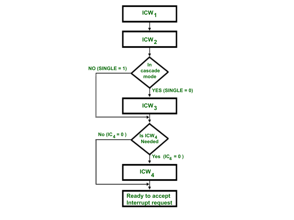
ICW1 command :
- The control word is recognized as ICW1 when A0 = 0 and D4 = 1.
- It has the control bits for Edge and level triggering mode, single/cascaded mode, call address interval and whether ICW4 is required or not.
- Address lines A7 to A5 are used for interrupt vector addresses.
When the ICW1 is loaded, then the initializations performed are:
- The edge sense circuit is reset because, by default, 8259 interrupt is edge triggered.
- The interrupt mask register is cleared.
- IR7 is assigned to priority 7.
- Slave mode address is assigned as 7.
- When D0 = 0, this means IC4 command is not required. Therefore, functions used in IC4 are reset.
- Special mask mode is reset and status read is assigned to IRR.
ICW2 command :
- The control word is recognized as ICW2 when A0= 1.
- It stores the information regarding the interrupt vector address.
- In the 8085 based system, the A15 to A8 bits of control word is used for interrupt vector addresses.
- In the 8086 based system, T6 to T3 bits are inserted instead of A15 to A8 and A10 to A8 are used for selecting interrupt level, i.e. 000 for IR0 and 111 for IR7.

Initialization of 8259 by ICW1 and ICW2 command words
ICW3 :
ICW3 command word is used when there is more than one 8259 present in the system i.e. when SNGL bit in ICW1 is 0, then it will load 8-bit slave register.

ICW3
ICW4 :
- When AEOI = 1, then Automatic end of interrupt mode is selected.
- When SFMN = 1, then a special fully nested mode is selected.
- when BUF = 0 , then Non buffered mode is used (i.e. M/S is don’t care) and when M/S = 1, then 8259 is master, otherwise it is a slave.
- when µPM = 1, then 8086 operations are performed, otherwise 8085 operations are performed.

ICW4
Operational command word(OCW) :
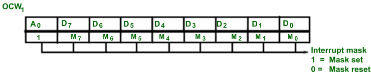
OCW1 –
It is used to set and reset the mask bits in IMR(interrupt mask register). M7 – M0 describes 8 mask bits
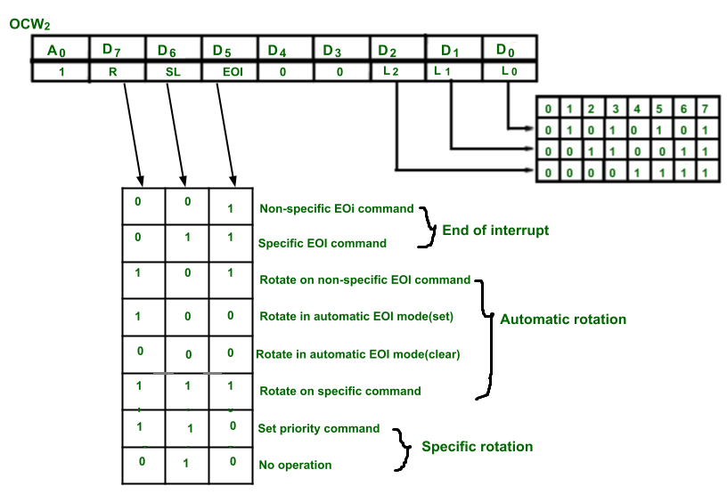
OCW2 –
It is used for selecting the mode of operation of 8259. Here L2 to L0 are used to describe interrupt level on which action need to be performed.
Detailed operations are described in the diagram below.
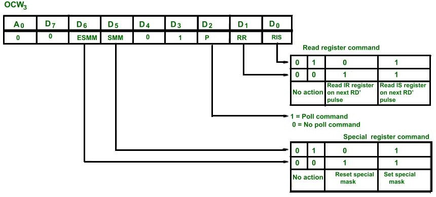
OCW3 –
- When the ESMM (Enable special mask mode ) bit is set, then the SMM bit is don’t care. If SMM = 1 and ESMM = 1, then 8259 will enter in Special mask mode.
- If ESMM = 1 and SMM = 0, then 8259 will return into normal mask mode.
- RR and RIS are used to give the read register command.
- P = 1 is used for poll command.
Like Article
Suggest improvement
Share your thoughts in the comments
Please Login to comment...