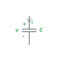
A two-terminal electrical device with its voltage-current relationship as its only distinguishing feature is represented mathematically as an idealized circuit element. Although ideal circuit elements are not “off-the-shelf” circuit components, their significance comes from the ability to be coupled to simulate real circuits made up of nonideal elements and other electrical components, allowing for the study of such circuits.
A circuit is an interconnection of elements. Based on their capability to generate energy these elements are classified into active or passive elements. Electric circuits are made up of three circuit components. These are resistance, inductance, and capacitance. These are called passive circuit elements and they do not transfer electrical energy. On the other hand, there are active elements like voltage and current sources which transfer electrical energy to the circuits.
Active and Passive Circuit elements:
Active Elements
The term “active element” refers to an independent source that can continually produce or absorb energy.
An independent voltage source is shown as,
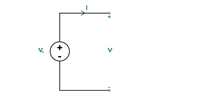
Active element
The ideal source’s voltage is considered to be independent of the circuit’s current. When current flows out of the positive terminal, the voltage source supplies power to the circuit; when current flows into the positive terminal, power is consumed. There is no limit to the amount of power that a perfect voltage source can provide or absorb.
Energy is given through a conversion process from another energy type in a practical voltage source, and the terminal voltage is slightly current-dependent. The practical voltage source has a very low internal resistance.
An independent current source is shown as,
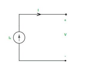
Independent Current Source
The current supplied by an ideal current source is voltage-independent. A practical current source is an ideal current source that is parallel and has a high internal resistance, and the current is also voltage-dependent based on the magnitude of the internal resistance.
Passive Elements
Elements like resistance, inductance, and capacitance are called passive elements.
1. Resistance :
Resistance is defined as the property of a substance that opposes the flow of charge or electricity through it. Conductors offer very little resistance and hence readily allow electricity to flow through them, whereas insulating materials offer such a high resistance that they allow practically no electricity to flow through them. The practical unit of resistance is the ohm (Ω). The resistance of a conductor will be 1Ω when it allows 1A current to flow through it on the application of 1V across its terminals.
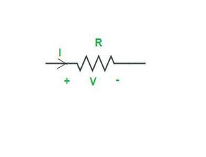
Resistor
Ohm’s law states that the voltage across a resistor equals the product of the current flowing through it and the resistance of the resistor. It may be expressed mathematically as
  V = IR
⇒ I = V/R
The resistance offered by a conducting material varies as follows:
- It is directly proportional to its length.
- It is inversely proportional to the conductor’s cross-sectional area.
- It depends on the nature of the material.
- It is also affected by the conductor’s temperature.
Thus, the resistance R offered by the conductor is given by,
R = ρl/A
where l is the length of the conductor, A is the cross-sectional area and ρ is a constant of the material, generally known as the specific resistance or resistivity of the material. The resistivity of a material depends on its nature and the temperature of the conductor, but not on its shape and size.
2. Inductance :
Inductance is the storage element that can store and deliver energy but its energy-handling capacity is limited. Inductor stores energy in the form of magnetic field. When a conductor is wound like a spring, then it is said to be a coil. The coil will exhibit ideally inductance(L) and practically some leakage resistance (R), which is modeled in series with the inductance. Henry is the practical unit of inductance (H). An inductor is a practical inductance.
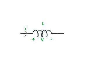
Inductor
When a time-varying current is flowing through the coil, a time-varying magnetic flux will be produced (by Faraday’s law). The total flux produced is
ψ = NΦ Weber

where N= number of turns
      Φ = flux per turn
The total flux generated is inversely proportional to the coil’s current.
i.e   ψ ∝ i ⇒ ψ = Li
where L = inductance parameter of the coil.
The inductance of an inductor or a coil depends on the following factors :
- It is directly proportional to the permeability of the magnetic material over which the coil is wound.
- It is directly proportional to the coil’s cross-sectional area.
- It is inversely proportional to the coil’s length.
- It is directly proportional to the square of the number of the coil.
3. Capacitance :
A Capacitor is a Passive element that stores energy in the form of electric field. It is a practical element that have the property of capacitance.
Farad is the unit of capacitance (F). A capacitor typically consists of two conducting plates that are separated by a dielectric material. The capacitor holds a positive charge when a positive voltage is placed across it. The capacitor also stores a negative charge when a negative voltage is placed across it. Capacitor only allows A.C current to pass through them and stops D.C Current. That’s why Capacitor is used to filter non-A.C Component of current.
Capacitor
As a result, the quantity of charge stored in the capacitor is proportional to the applied voltage V across it, and the relationship is linear. It may be expressed mathematically as
   Q ∝ V
⇒ Q = CV

where C = the conductor's capacitance
      Q = the charge held in a capacitor.
The capacitance of a capacitor is determined by the following factors:
- It is directly proportional to the surface area of the plate.
- The distance between the two plates is inversely proportional to it.
- It is proportional to the medium’s permittivity between the two plates.
- It is directly proportional to the permittivity of the medium between the two plates.
Energy Sources
Energy sources are classified as :
Independent Sources
(i) Voltage Source
A voltage that is maintained by an independent voltage source is either fixed or varies over time and is unaffected by any other quantity.
Ideal Voltage Source :
A two-terminal component having the feature that the voltage between the terminals is predetermined at each point in time is an ideal voltage source. The current flowing from the source has no bearing on this voltage. The internal resistance of an ideal voltage source is zero.
An ideal voltage source and its v-i characteristics are as follows :
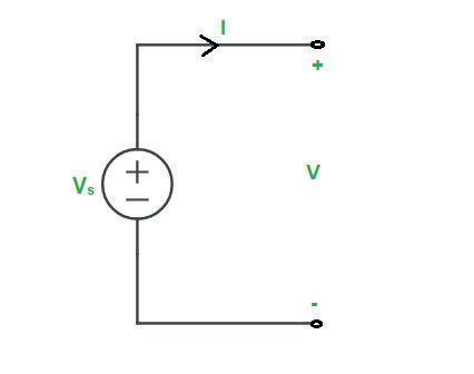
Ideal Voltage Source
Practical Voltage Source :
An ideal voltage source (Vs) is connected in series with a low internal resistance (Rs) to form a practical voltage source. A practical voltage source and its v-i characteristics are as follows :
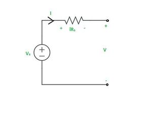
Practical Voltage Source
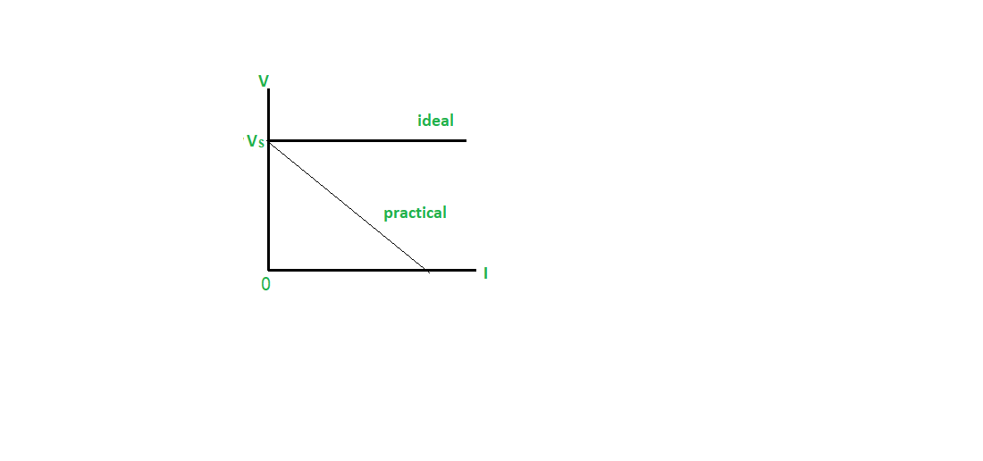
IV Graph
(ii) Current Source
A current that is maintained by an independent current source is either fixed or varies over time and is unaffected by any other quantity.
Ideal Current Source :
An ideal current source is, by definition, a two-terminal element having the property that the current flowing through the device is defined at every point in time. This current is unaffected by the voltage across the source. The resistance of the ideal current source is infinite. Zero conductance is equivalent to infinite resistance. As a result, the ideal current source has no conductance.
An ideal current source and its v-i characteristics are as follows :
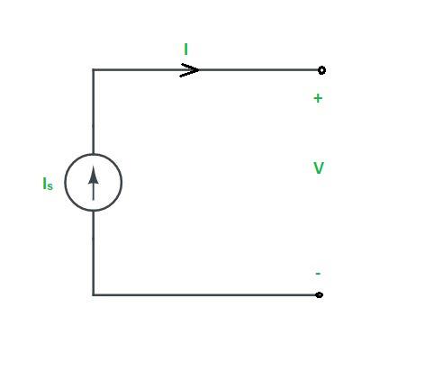
Ideal Current Source
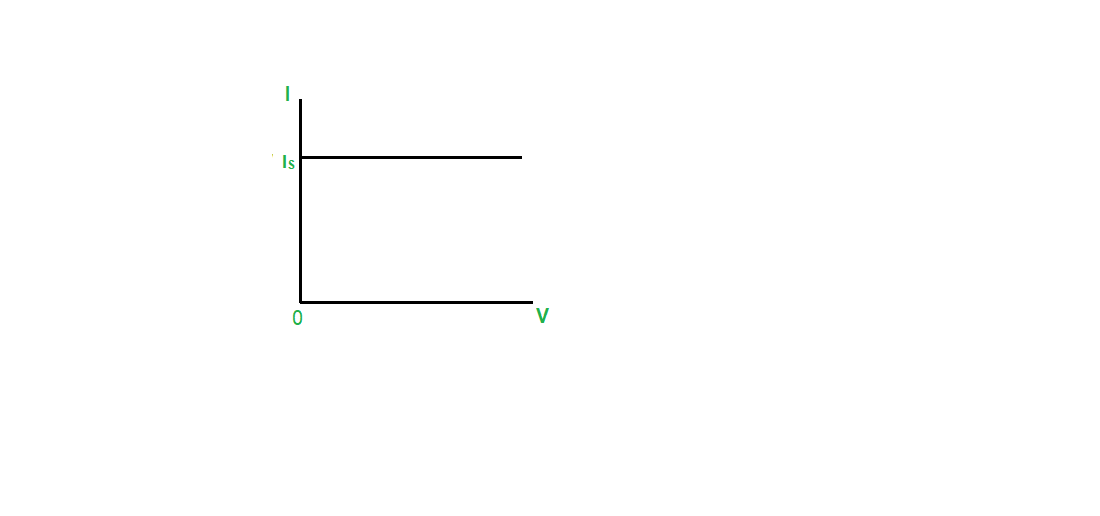
IV Graph
Practical Current Source:
An ideal current source (Is) is connected in parallel with a high internal resistance (Rs) or low conductance to form a practical current source. A practical current source and its v-i characteristics are as follows :
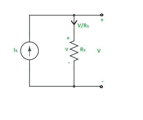
Practical Current Source
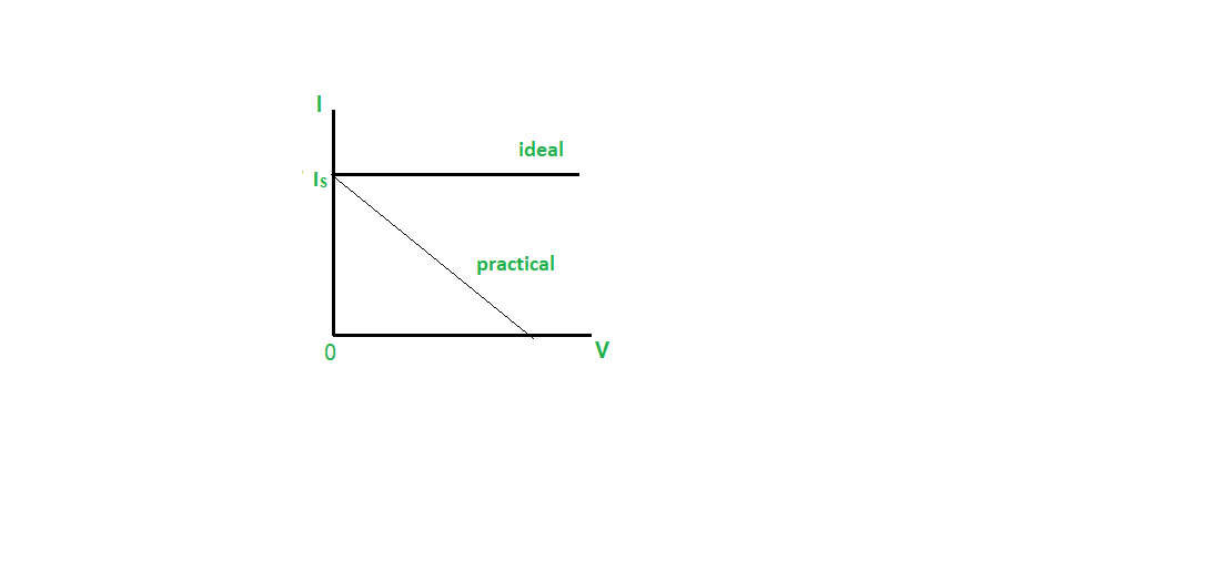
IV Graph
Dependent or Controlled Sources
A dependent source is a current or voltage source that depends on another circuit’s current or voltage rather than having a fixed value (i.e., independence). There are four types of dependent sources. They are as follows :
- Voltage-Controlled Voltage Source (VCVS)
- Current-Controlled Voltage Source (CCVS)
- Voltage-Controlled Current Source (VCCS)
- Current-Controlled Current Source (CCCS)
- With respect to controlled variables only, the dependent source is said to be linear, active, and bilateral. The presence of these elements makes the network linear, active and bilateral.
- Controlled sources are said to be sources i.e. active elements in the presence of at least one independent source, then only controlled variables are non zero and hence their magnitudes are not zero.
Like Article
Suggest improvement
Share your thoughts in the comments
Please Login to comment...