Binary Decoder in Digital Logic
Last Updated :
06 May, 2023
A binary decoder is a digital circuit that converts a binary code into a set of outputs. The binary code represents the position of the desired output and is used to select the specific output that is active. Binary decoders are the inverse of encoders and are commonly used in digital systems to convert a serial code into a parallel set of outputs.
- The basic principle of a binary decoder is to assign a unique output to each possible binary code. For example, a binary decoder with 4 inputs and 2^4 = 16 outputs can assign a unique output to each of the 16 possible 4-bit binary codes.
- The inputs of a binary decoder are usually active low, meaning that only one input is active (low) at any given time, and the remaining inputs are inactive (high). The active low input is used to select the specific output that is active.
- There are different types of binary decoders, including priority decoders, which assign a priority to each output, and error-detecting decoders, which can detect errors in the binary code and generate an error signal.
In summary, a binary decoder is a digital circuit that converts a binary code into a set of outputs. Binary decoders are the inverse of encoders and are widely used in digital systems to convert serial codes into parallel outputs.
In Digital Electronics, discrete quantities of information are represented by binary codes. A binary code of n bits is capable of representing up to 2^n distinct elements of coded information. The name “Decoder” means to translate or decode coded information from one format into another, so a digital decoder transforms a set of digital input signals into an equivalent decimal code at its output. A decoder is a combinational circuit that converts binary information from n input lines to a maximum of 2^n unique output lines. 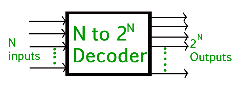
Binary Decoder –
- Binary Decoders are another type of digital logic device that has inputs of 2-bit, 3-bit or 4-bit codes depending upon the number of data input lines, so a decoder that has a set of two or more bits will be defined as having an n-bit code, and therefore it will be possible to represent 2^n possible values.
- If a binary decoder receives n inputs it activates one and only one of its 2^n outputs based on that input with all other outputs deactivated. If the n -bit coded information has unused combinations, the decoder may have fewer than 2^n outputs.
- Example, an inverter ( NOT-gate ) can be classified as a 1-to-2 binary decoder as 1-input and 2-outputs is possible. i.e an input A can give either A or A complement as the output.
- Then we can say that a standard combinational logic decoder is an n-to-m decoder, where m <= 2^n, and whose output, Q is dependent only on its present input states.
- Their purpose is to generate the 2^n (or fewer) minterms of n input variables. Each combination of inputs will assert a unique output.
A Binary Decoder converts coded inputs into coded outputs, where the input and output codes are different and decoders are available to “decode” either a Binary or BCD (8421 code) input pattern to typically a Decimal output code. Practical “binary decoder” circuits include 2-to-4, 3-to-8 and 4-to-16 line configurations.
2-to-4 Binary Decoder –
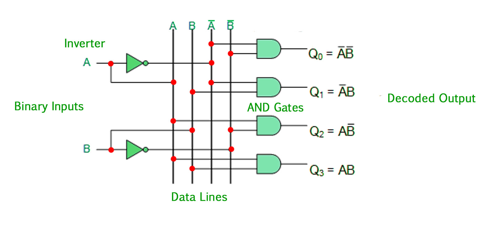 The 2-to-4 line binary decoder depicted above consists of an array of four AND gates. The 2 binary inputs labeled A and B are decoded into one of 4 outputs, hence the description of a 2-to-4 binary decoder. Each output represents one of the minterms of the 2 input variables, (each output = a minterm).
 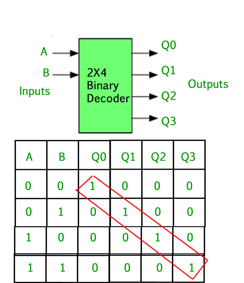 The output values will be: Qo=A’B’ Q1=A’B Q2=AB’ Q3=AB The binary inputs A and B determine which output line from Q0 to Q3 is “HIGH” at logic level “1” while the remaining outputs are held “LOW” at logic “0” so only one output can be active (HIGH) at any one time. Therefore, whichever output line is “HIGH” identifies the binary code present at the input, in other words, it “decodes” the binary input. Some binary decoders have an additional input pin labeled “Enable” that controls the outputs from the device. This extra input allows the outputs of the decoder to be turned “ON” or “OFF” as required. The output is only generated when the Enable input has value 1; otherwise, all outputs are 0. Only a small change in the implementation is required: the Enable input is fed into the AND gates which produce the outputs. If Enable is 0, all AND gates are supplied with one of the inputs as 0 and hence no output is produced. When Enable is 1, the AND gates get one of the inputs as 1, and now the output depends upon the remaining inputs. Hence the output of the decoder is dependent on whether the Enable is high or low. GATE CS Corner Questions Practicing the following questions will help you test your knowledge. All questions have been asked in GATE in previous years or in GATE Mock Tests. It is highly recommended that you practice them.
- GATE CS 2007, Question 85
- GATE CS 20130, Question 65
Advantages of using Binary Decoders in Digital Logic:
- Increased flexibility: Binary decoders provide a flexible way to select one of multiple outputs based on a binary code, allowing for a wide range of applications.
- Improved performance: By converting a serial code into a parallel set of outputs, binary decoders can improve the performance of a digital system by reducing the amount of time required to transmit information from a single input to multiple outputs.
- Improved reliability: By reducing the number of lines required to transmit information from a single input to multiple outputs, binary decoders can reduce the possibility of errors in the transmission of information.
Disadvantages of using Binary Decoders in Digital Logic:
- Increased complexity: Binary decoders are typically more complex circuits compared to demultiplexers, and require additional components to implement.
- Limited to specific applications: Binary decoders are only suitable for applications where a serial code must be converted into a parallel set of outputs.
- Limited number of outputs: Binary decoders are limited in their number of outputs, as the number of outputs is determined by the number of inputs and the binary code used.
In conclusion, binary decoders are useful digital circuits that have their advantages and disadvantages. The choice of whether to use a binary decoder or not depends on the specific requirements of the system and the trade-offs between complexity, reliability, performance, and cost.
Application of Binary Decoder in Digital Logic:
1.Memory tending to: In computerized frameworks, paired decoders are generally used to choose a particular memory area from a variety of memory areas. The location inputs are applied to the double decoder, and the comparing memory area is chosen.
2.Control circuits: Parallel decoders are utilized in charge circuits to produce control signals for various tasks. For instance, in a microchip, a double decoder is utilized to translate the guidance opcode and produce control signals for the comparing activity.
3.Display drivers: In computerized frameworks that utilization show gadgets, for example, Drove shows, parallel decoders are utilized to drive the presentation. The double data sources are applied to the decoder, and the relating Drove is enlightened.
4.Address unraveling: Parallel decoders are utilized in address disentangling circuits to create the chip select sign for a particular memory or fringe gadget.
5.Digital correspondence: Twofold decoders are utilized in advanced correspondence frameworks to unravel the computerized information got over the correspondence channel.
6.Error rectification: Double decoders are utilized in mistake amendment circuits to recognize and address blunders in computerized information.
References –
Here are a few books that you can refer to for further information on digital logic and binary decoders:
- “Digital Systems Design Using VHDL” by Charles H. Roth Jr. and Lizy Kurian John
- “Digital Design and Computer Architecture” by David Harris and Sarah Harris
- “Principles of Digital Design” by Daniel D. Gajski, Frank Vahid and Tony Givargis
- “Digital Circuit Design: An Introduction” by Thomas L. Floyd and David Money Harris
- “Digital Fundamentals” by Thomas L. Floyd
These books cover various topics in digital logic and design, including binary decoders, and provide in-depth information on the theory, design, and implementation of digital circuits.
electronicshub – Binary Decoder
Like Article
Suggest improvement
Share your thoughts in the comments
Please Login to comment...