Binary Decision Diagram
Last Updated :
01 Nov, 2022
Binary Decision Diagram (BDD) is an effective way to represent the Switching function. It is a Data-Structure used to represent a Boolean Function and can be represented as a compressed form of sets or relations.
Definition:
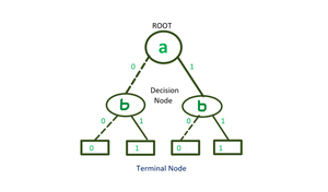
A BDD is a set of an Acyclic, Rooted Graph with Directed Edges(Top-to-Bottom), which consist of Decision Node and 2-Terminal Nodes and have a special Node Called ROOT.
A binary decision diagram is a rooted, directed, acyclic graph. Nonterminal nodes in such a graph are called decision nodes; each decision node is labeled by a Boolean variable and has two child nodes, referred to as low child and high child.
BDD is a Shannon cofactor tree:
- f = v fv +v’ fv’ (Shannon expansion)
- Vertices represent decision nodes (i.e. multiplexers) controlled by variables
- leaves are constants “0” and “1”
Representation of BDD:
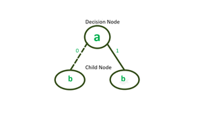
Decision and Child Node
- Each Decision Node is labeled by a Boolean variable and has two child nodes called low child and high child.
- The edges from a node to a low child represent, an assignment of variable 0 and for high as 1.
Representation of BDD
- Every Decision Node with a variable a and has two child nodes.
A BDD is said to be Ordered if different variables appear in the same order on all paths from the root.
A three-variable function is represented by Truth-table and BDD.
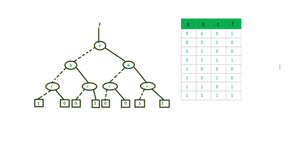
BDD of Three-variable function
Variable ordering restriction and reduction rules make (ROBDD) representation canonical
Example:
f = ac+bc+a'b'c
Solution-
Step -1: Decomposing the function with respect to variable a
for a’ put a=0 & for a put a=1 in function;
Now, we get-
f =  a' (b'c'+bc) + a(c+bc)
f =  a'(b'c'+bc) + a(c)
Step – 2: Decomposing the functions with respect to variable b-
- decompose (b’c’+bc) w.r.to b = b'(c’)+b(c)
- decompose (c) w.r.To b = b'(c)+b(c)
Step – 3: Decomposing the functions with respect to variable c-
- decompose c’ w.r.to c = c'(1)
- decompose c w.r.to c = c(0)
- decompose c’ w.r.to c’ = c'(0)
- decompose c w.r.to c’ = c(1)
We get:
c'(1)+c(0) c'(0)+c(1) c'(0)+c(1) c'(0)+c(1)
Note: Here order of variables is a, b, c. But we can take variables in any order.
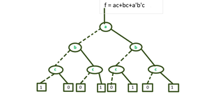
BDD of f=ac+bc+a’b’c
Logical Operation in BDD
Conjunction(∧) – AND
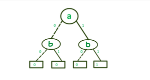
BDD of ( a∧ b)
In mathematical notation, we usually write a ∧ b.
In the diagram above for a ∧ b, we indicate the 0 (left) branch with a dashed line and the 1 (right) branch with a solid line. This convention will make it easier to draw diagrams without a lot of intersecting lines.
Disjunction( ∨ ) – OR
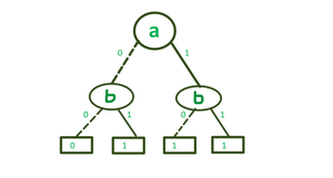
BDD of ( a ∨ b)
In mathematical notation, we usually write a ∨ b.
Negation(⊕ )– NOT
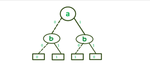
BDD of ( a⊕ b )
Exclusive or, which is mathematically often written as a⊕ b.
Variable Ordering in BDD:
The size of BDD is determined both by the function being represented and the chosen ordering of the variables.
For some functions, the size of a BDD may vary between a linear to an exponential range depending upon the ordering of the variables.
Example:
f(x1,.......,x2n) = x1x2+ x3x4+.......+x2n-1x2n
Variable Ordering: x1 < x3 <……<x2n-1< x2 < x4<……< x2n
BDD requires 2n+1 nodes to represent the function.
Variable Ordering: x1<x2<x3<x4<x5<……..<x2n-1<x2n
BDD requires 2n nodes to represent the function.
Application of BDD:
- BDDs are extensively used in CAD software to synthesize circuits (logic synthesis) and in formal verification.
- In the analysis of Digital Circuit.
- There are several lesser-known applications of BDD, including fault tree analysis, Bayesian reasoning, product configuration, and private information retrieval.
Share your thoughts in the comments
Please Login to comment...