When often asked, how does an airplane generate lift or how the really cool paint-spray guns work, the most common answer is the Bernoulli’s Principle – a seemingly simple two worded answer to a frankly multi-layered phenomenon. This concept of Fluids and their mechanical properties might seem a heavy topic to understand, largely due to the lengthy equations of derivation and unappealing representations. However, remember that comprehending the idea is key. Visualizing the concept can do wonders for any problem solver.
In this article, we shall help build the definition and perspective of Bernoulli’s Principle and therefore the associated equation (like everything that was ever explained in physics – using equations).
Bernoulli’s Principle
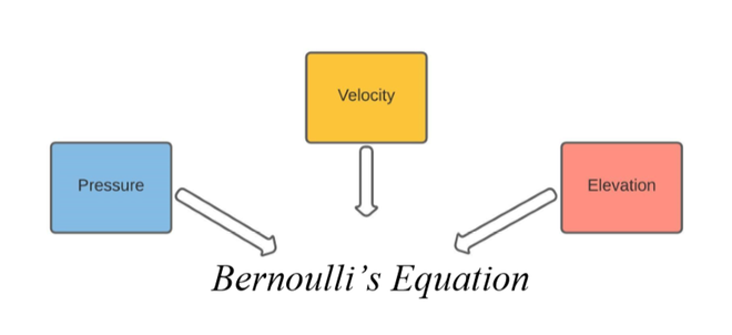
As shown above, Bernoulli’s equation is simply a mathematical expression that helps relate the velocity, pressure, and elevation of a fluid. This relation was built keeping in mind that energy is conserved throughout the motion of the fluid. We, therefore, look at the forms of energy associated with the fluid.
- Energy due to fluid pressure (static pressure): this is simply the energy of the system when the fluid is static and offers pressure to the walls of the container. It is effectively the static pressure.
- Kinetic Energy due to fluid motion: the evident energy associated with any mass in motion – here the motion of the fluid results in the existence of this form of energy. Another way of interpreting this is the energy associated with dynamic pressure.
- Gravitational potential energy from the elevation: potential energy is a rather referential concept. Here the elevation of the fluid accounts for the accumulation of such a potential energy. In other words, this arises due to hydrostatic pressure.
Therefore, by definition:
The total mechanical energy – which is defined as the sum of all these energies (kinetic, gravitational potential and fluid), must stay constant unless any work is done on the system. This is the Bernoulli’s Principle.
Hence, the following expression may be written:

The most evident relation that may be made using this expression is the kind of proportionality between a fluid’s pressure and its velocity. At any specific elevation which is constant, the gravitational potential energy may also be taken as a constant. In consequence, we are left with the following expression and understanding.
P + (½)ρv2 = k
∴ P = k – (½)ρv2
As P increases, v decreases.
Clearly, pressure and velocity are inversely proportional. This idea will be applied further on in the subsequent sections. Note that we’re still reeling around the principle. We need to derive the equation so that we can deal with different instances of the same system.
Bernoulli’s Equation
Since it has been established that Bernoulli’s Principle is a manifestation of the Conservation of Energy principle, we shall proceed by considering the work done to move the fluid along a streamline from one point to another. We represent the density of the fluid by ρ.
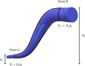
Fluid flows from Point A to Point B
We assume that the fluid at points A and B is elevated at heights of h1 and h2, respectively. It’s apparent that the gravitational potential energy at h2 is greater. Also, observe that the cross-sectional area at Point A is A1 and at Point B is A2. Now, if some work is to be done, the fluid would have to move a certain distance, implying an associated velocity as well.
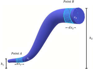
If the fluid moves by dx1 from point A and by dx2 from point B, it shall do so by attaining a velocity of v1 and v2, respectively. We shall work out our derivation along with the following expression:
dW = d(Kinetic Energy of Fluid) + d(Gravitational Potential of Fluid)
or
dW = dK + dU
The work done by the fluid when moving from Point A to Point B as dW = dW1 – dW2. Since the fluid is displaced by dx1 and dx2, we rewrite the expression in terms of the forces experienced at points A and B.
dW = F1.dx1 – F2.dx2 = P1.A1.dx1 – P2.A2.dx2
F1 and F2 are the forces experienced by the fluid at points A and B, respectively. Now, recall that Force is the Pressure experienced per unit Area. The expression for dW then can be modified. Note that A1dx1 = A2dx2 = differential volume (elemental/small volume), since any area multiplied by an adjacent length gives a volume. Let’s say that dV is the differential volume.
dW = P1.dV – P2.dV = (P1-P2).dV
Meanwhile, the expression for the Kinetic Energy of the Fluid can be written using the masses and velocities of the fluid at A and B. We shall use the standard expression for Kinetic Energy associated with a mass in motion i.e., dK = 0.5m2v22 – 0.5m1v12
Call to mind that we have been given the fluid density (ρ) and the differential volumes of fluid (dV). Since we would like to work with fewer terms, we may use the above to express masses of the fluid at points A and B alternatively. Therefore, we have:
dK = ½ρdV (v22 – v12)
The associated Gravitational Potential Energy is rather straightforward. Once again, we may simplify it further by expressing the masses alternatively i.e., Mass is Density times Volume. The GPE is denoted by dU.
dU = m1gh1 – m2gh2 = ρdVg (h2 – h1).
By equating the two sides of the equation (dW = dK + dU), we obtain the subsequent expression:
(P1 – P2)dV = ½ρdV (v22 – v12) + ρdVg (h2 – h1)
P1 – P2 = ½ρv22 – ½ρv12 + ρgh2 – ρgh1

This is in fact the Bernoulli’s Equation.
In deriving this expression, we did make a few assumptions in order to crop out the dynamicity of the problem. One quite significant assumption is the incompressibility of the fluid. This property allowed us to make the density invariable in relation to the pressure at different points of the pipe. How this affected our equation has been explained below.
Equation of Continuity
The change in density – even slightly if not so considerably – is quite commonplace in reality. Therefore, no fluid is perfectly incompressible. You may say that a liquid is much more incompressible than gas but not literally incompressible. That being said, this affects the mass of the fluid considered for the Energy calculations.
Since the density remains constant throughout, the sampled mass also remains equivalent as long as the volumes also stay equivalent – the volumes used in the calculations above were differential/elemental i.e., dV, and hence equal. As a result, our masses were equal. How can we understand this better?
A different perspective: Conservation of Mass
Consider the diagram below.
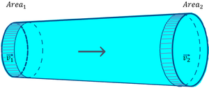
The next few lines in this article will closely adhere to the idea of Conservation of Mass – the rate at which a certain mass flows into the pipe at the beginning must be the same as the rate at which it leaves the pipe. This is crucial.
Rate at which mass enters = Rate at which the mass leaves
Mass is essentially density (ρ) times volume. So, we may express the masses in those terms and equate the different instances of flow – at the beginning and at the end. The velocities will certainly differ on account of different pressures. So far we have,
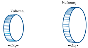
ρdV1 = ρdV2
where V1 is the volume at the beginning (a left bit of the pipe). V2 is the volume at the end (right-most shaded region). Do not confuse them with the velocities v1 and v2. The volumes may be visualized as cylinders, in terms of their cross-sectional area and height – cylinders have a volume expressed as cross-sectional area x-height of their body. So, if the cylinders have heights of dx1 and dx2,
ρA1dx1 = ρA2dx2
Since, we are dealing with the ‘RATE’ of mass, we will be measuring the flow in equal intervals of time, Δt. We may express the displacement in terms of the velocity of the fluids v1 and v2.
ρ.A1.v1.Δt = ρ.A2.v2.Δt
∴ A1v1 = A2v2
This is the Equation of Continuity. It comes in handy when dealing with several applications of Bernoulli’s Principle.
Applications of Bernoulli’s Principle
(1) Crashing Ships
A terrifying tale of the past, two ships crashing into each other when traveling parallel to each other is a classic example of Bernoulli’s Principle at play.
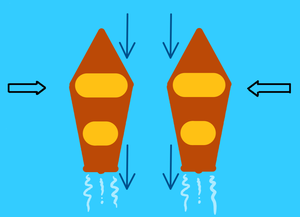
Higher Pressure on the outside of the boats leads to a collision
Imagine two boats sailing parallel to each other at equal velocities. Since the middle portion of the boat is the widest, it acts as a funnel or squeezed pipe for the water between the two boats. This decrease and increase in the area for the water to pass through leads to an increase in velocity (Bernoulli’s Principle). However, once the velocity increases, the pressure between the boat decreases. As a result, in order to stabilize this lower pressure the water on the outside pushes inward causing the boats to move towards each other.
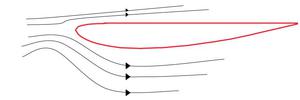
(2) Airfoils and Lift
Many attribute the reason behind flight only to the Bernoulli Principle. However, another principle – Coanda Effect – is also at play when it comes to generating the required amount of lift force for an airplane to take off.
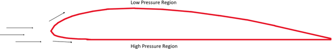
The incident air must pass over and under the airfoil. In doing so, the air travels an extra distance over the top of the wing. In accordance with the Coanda effect, the air travels faster along curved surfaces. So, the air is at a higher velocity than the airfoil. As per Bernoulli’s Principle, a higher velocity of the fluid leads to a corresponding lower pressure region. Meanwhile, the pressure under the airfoil is relatively higher. This difference in pressures leads to an upward force – Lift Force – which is the sole reason behind flight and the structures of wings on aircraft.
(3) Deviation of a Spinning Ball from its Trajectory
Any ball when thrown normally (without any spin) is observed to succumb to the effects of gravity and outline a parabolic trajectory. However, when the ball is provided a spin, it deviates from its trajectory and rises or falls depending on the direction of spin and relative air.
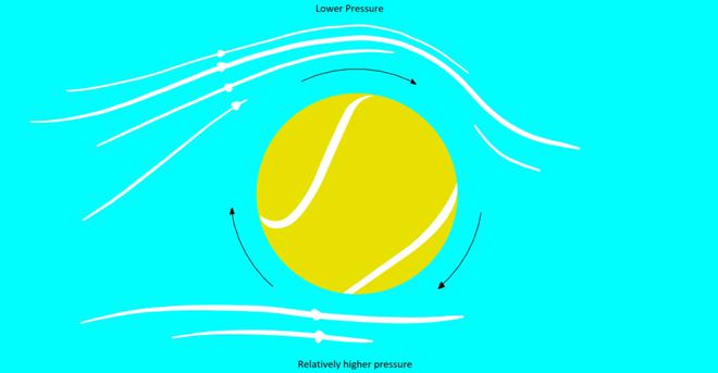
When the ball is spun and the air is moving towards the ball, the streamline of the air is dragged along with the ball, which is what we see on the top half of the figure above. Meanwhile, the direction of air below the ball is against the spin which leads to minimal drag (the streamline continues normally). Since the air above must traverse a greater distance over and along with the ball, it must do so with greater velocity. A higher velocity is associated with lower pressure as per Bernoulli’s Principle. This difference in velocities and subsequently the generated pressures leads to a Dynamic Lift causing the ball to rise. This effect is also known as the Magnus Effect which is a major topic in all ball sports since the action of spinning leads to a deviated motion (desired or undesired depending on the circumstances).
Sample Problems
Problem 1. Now that we have an idea about how Bernoulli’s Principle is used to explain flight, how would you explain flight when an aircraft is flying upside-down?
Solution:
Consider an airfoil, except inverted along the x-axis.
The confusing bit lies in how there is a lower pressure region underneath due to higher velocity along the streamlines. Also, the air is slower above which means the plane would logically crash as it is pushed downwards! Here’s the clever bit though. Airplanes such as stunt planes or fighter aircraft often resort to symmetrical wings which may tilt to provide lift. Since they are largely symmetrical, the velocities above and below are relatively equal. However, to generate the lift, tilting the wings upward by a minute angle helps keeping the plane in flight. This tilt is also sometimes known as the angle of attack.
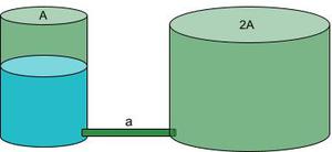
Problem 2: Two cylindrical tanks having cross-sectional areas A and 2A respectively are kept on a horizontal floor. The first tank is filled to a height of H while the other is empty. If they are connected by a pipe with negligible cross-sectional are ‘a’ at the bottom at time t=0, find how long it would take for the heights in the two tanks to become equal.
Solution:
Take the cylinder on the left as point 1, the pipe as point 2, and the cylinder on the right as pipe 3. Many students make the mistake of directly applying Bernoulli’s equation between the two cylinders. This is incorrect since there is a loss of energy when liquid flows from the pipe to cylinder 3 due to inelastic collisions when the liquid collides with some mass of the liquid in cylinder 3 as it fills up (look below).
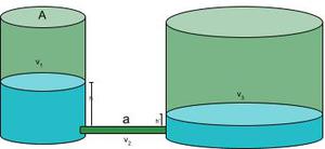
There is conservation of energy only between cylinder 1 and the pipe. However, there is conservation of mass throughout! This means we may use the equation of continuity. Therefore, we have the following:
A1v1 = av2 = A2v3 (equation of continuity)
Now, take the difference in heights to be y i.e., h – h’ = y
We need this difference to equal 0 as the heights will be equal at some point. The rate or how quickly this happens can be written as a differential.
dy/dt = -(v1 + v3) ……………v1 is downwards and v3 is upwards)
⇒ dy/dt = -v1(1+A1/A2) ………by taking v1 common and writing v3/v1 using the equation of continuity.

Now, let’s apply Bernoulli’s Equation between cylinder 1 and the pipe:
P1 + (1/2)ρv12 +ρgh = P2 + (1/2)ρv22 + ρgh’
⇒ ρg(h – h’) = (1/2)ρv12((A12/a2) – 1) ……………by rearranging and using the equation of continuity for (v2/v1).

In the previous step we are approximating ((A12/a2) – 1) to A1/a since a<<A1. In the next step we shall integrate the differential equation by bringing dy to one side and dt on the other.

The limits for y tend from H to 0 since we want the differences in heights to equal 0 at the end.
Time elapsed would be = 
Problem 3: Water flows through a horizontal pipe with a cross-sectional area of 4 m2 at 5 m/s with a pressure of 0.3 MPa at point A. At point B, the cross-sectional area is 2 m2. What is the speed of the water at point B? Calculate the pressure at point B.
Solution:
Let’s visualize the case presented to us.
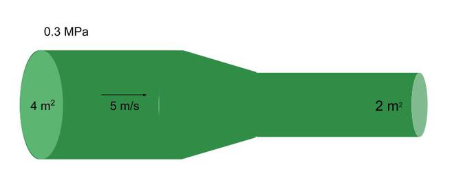
Using the equation of continuity, we can solve for the speed at point B. A1 x v1 = A2 x v2
Therefore, v2 = (A1 x v1)/A2
⇒ v2 = (4 x 5)/2 m/s = 10 m/s
Now let’s calculate the velocity at point B. Notice how the velocity has increased. This means the pressure would decrease in proportion – as per Bernoulli’s Principle. This will help us verify our answer. Using Bernoulli’s Equation:
P1 + (1/2)ρv12 + ρgh = P2 + (1/2)ρv22 + ρgh ……….since the fluid’s elevation is the same.
⇒ 0.3×10⁶ + 0.5x1000x25 = P2 + 0.5x1000x102
⇒ P2 = 0.2625 MPa
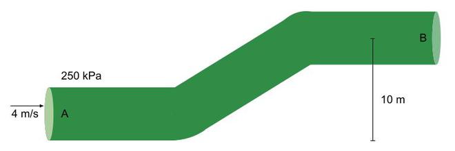
Problem 4. Water flows through a pipe of constant radius = 10 cm with a speed of 4 m/s and a pressure of 250 kPa. Find the speed at the outlet and mention which conservation law is used in this calculation. What is the pressure at point B?
Solution:
If the radius of the pipe stays constant throughout, the cross-sectional area of the outlet would stay the same. Based on the equation of continuity, A1 x v1 = A2 x v2, since the areas are the same, the speed of the water at the outlet is 4 m/s. v2 = 4 m/s . The equation of continuity is based on the Conservation of Mass.
Using the Bernoulli’s Equation, substitute the values of pressure velocity and height at point A and the velocity and elevation at point B. Take fluid density as 1000 kg/m3.
⇒ 250 kPa + 0.5x1000x16 + 1000×9.8×0 = P2 + 1000×9.8×10 + 0.5x1000x16
⇒ P2 = 152 kPa
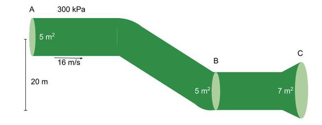
Problem 5: Refer to the figure below and arrange the pressures at points A, B, and C in ascending order. Do the same for the speeds at points A, B, and C.
Solution:
Let’s calculate the speeds first. We know that va = 16 m/s. Since the areas at point A and point B are the same, the velocities will also remain the same. Many students may find this confusing since speed increases as you fall down. However, in this case, the pressure is increasing due to a change in height – remember to take note of this. So, vb = 16 m/s
Using the equation of continuity, Ab x vb = Ac x vc . Therefore, vc = (5/7) x 16 m/s = 11.429 m/s.
⇒ va = vb > vc
Now we can find the pressure at point B using the speeds obtained. From Bernoulli’s equation between A and B, we can find the pressure at point B.
Pa + (1/2)ρva2 + ρgh = Pb + (1/2)ρvb2 + ρgh , since the speeds at point A and B are the same.
⇒ 300 kPa + 1000×9.8×16 = Pb + 1000×9.8×0
⇒ Pb = 156.8 kPa
Using Bernoulli’s Equation between points A and C we get the following:
Pa + (1/2)ρva2 + ρgh = Pc + (1/2)ρvc2 + ρgh ⇒ 300 + 0.5x1000x256 + 1000×9.8×20 = Pc + 0.5x1000x(11.429)2 + 1000×9.8×0
⇒ Pc = 258.9 kPa
⇒ Pa < Pb < Pc
Question 6. A house is designed to withstand huge torrents of wind with maximum speeds of 80 m/s. The surface area of the roof is A = 450 m. How much force can the roof supports withstand? Take air density = 1.029 kg/m3
Solution:
Assume two points around the roof – one outside and the other inside. On a larger scale, the distance between the points would be quite small. Refer to the figure below.
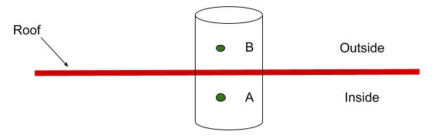
Logically, we must not feel the winds inside the house. So we may assume the velocity inside or va = 0. Since, the points are quite close to eachother, they may be assumed as elevated at the same height. Our Bernoulli’s Equation is now quite simple.
⇒ PA + (1/2)ρvA2 + ρgh = PB + (1/2)ρvB2 + ρgh
Since vA = 0, ⇒ PA – PB = (1/2)ρvB2
⇒ ΔP = (1/2)ρvB2
⇒ Force / Area of Roof = ΔP
⇒ Force = 0.5ρvB2 x Area
⇒ Force = 0.5 x 1.029 x 802 x 450
The roof can withstand a maximum force of 1.481 x 10⁶ N.
Like Article
Suggest improvement
Share your thoughts in the comments
Please Login to comment...