Analysis and Design of Combinational and Sequential circuits
Last Updated :
12 Apr, 2020
1. Analysis and Design of Combinational circuits:
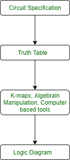
To design of combinational circuits, the procedure involves the following steps:
- Find the required number of inputs and outputs and assign a symbol to each.
- Derive the truth table according to given specifications and function.
- Using the truth table, obtain simplified Boolean functions for each output as a function of the input variables.
- Draw the logic circuit diagram.
To obtain the output Boolean functions from a logic diagram, the procedure involves the following steps:
- Label all gate outputs with unique symbols.
- Find the Boolean functions for these gates.
To obtain the truth table directly from the logic diagram, the procedure involves the following steps:
- Determine the number of input variables in the circuit.
- Draw the table for these inputs. There are 2^n combinations for the n input variables (0 to (2^n -1)).
- Label the outputs with unique symbols for gates in the circuit.
- Obtain the outputs of these gates in the table.
Drawbacks of Combinational circuits:
If you need to design a system that stores and uses previous input and output, then we can not use a combinational circuit because it doesn’t have capability to store any state or depend clock or and time. For these properties you can use Sequential circuits.
2. Analysis and Design of Sequential circuits:
To design of Sequential circuits, the procedure involves the following steps:
- Derive the state table and state equations.
- Derive the state diagram using the state table.
- Reduce states using state reduction technique.
- Verify the number of Flip-Flops and type of Flip-Flop to be used.
- Derive the excitation equations using the excitation table.
- Derive the output function and the Flip-Flop input functions.
- Derive the logic functions or equation for each output variable.
- Draw the required logic diagram.
Examples of sequential circuits are Registers, Shift Registers, Counters, Ripple Counters, Synchronous Counters etc.
Like Article
Suggest improvement
Share your thoughts in the comments
Please Login to comment...