Addition of two 8-bit numbers in 8051 Microcontroller Using Ports
Last Updated :
24 Apr, 2023
Introduction:
To perform addition of two 8-bit numbers using ports in 8051 microcontroller, we need to connect the two 8-bit numbers to be added to two ports of the microcontroller. We can use any two ports of the microcontroller, for example, P1 and P2.
The first step is to load the two numbers into two different ports. For example, we can load the first number into port P1 and the second number into port P2. We can use the MOV instruction to load the numbers into the ports.
Once the numbers are loaded into the ports, we can use the ADD instruction to add the two numbers. The ADD instruction adds the contents of the accumulator and the specified operand and stores the result in the accumulator. Since the two numbers are already loaded into the ports, we can simply use the ADD instruction with the accumulator and the appropriate port.
After the addition is complete, we can retrieve the result from the accumulator and store it in another port or memory location for further processing or display.
8051 microcontroller is a microcontroller designed by Intel in 1981. It is an 8-bit microcontroller with 40 pins DIP (dual inline package), 4kb of ROM storage and 128 bytes of RAM storage, 2 16-bit timers. It consists of four parallel 8-bit ports, which are programmable as well as addressable as per the requirement.
Issues in Addition of two 8-bit numbers 8051 Microcontroller Using Ports :
There are several issues that can arise when performing addition of two 8-bit numbers in 8051 microcontroller using ports:
- Overflow: If the result of the addition exceeds 8 bits, the carry flag (CY) in the program status word (PSW) will be set. If this flag is not checked before storing the result, the result may be incorrect.
- Input validation: Before performing the addition, it is important to validate the input to ensure that the numbers are within the range of 0 to 255. If the input is not validated, the result may be incorrect.
- Port initialization: The ports used for input and output must be properly initialized before use. If the ports are not properly initialized, the data may not be transferred correctly.
- Endianness: The order in which the bytes of the numbers are stored in memory can affect the result of the addition. It is important to ensure that the bytes are stored in the correct order before performing the addition.
- Interrupts: If interrupts are enabled during the addition operation, the result may be affected. It is important to disable interrupts during critical operations to ensure the correct result.
- Timing: The timing of the addition operation can affect the result. It is important to ensure that the necessary delays are added between instructions to ensure correct operation.
- Code optimization: The code used to perform the addition should be optimized to ensure that it uses the least number of instructions and takes the least amount of time. This is important to avoid potential timing issues and to ensure that the microcontroller can perform other tasks while the addition is being performed.
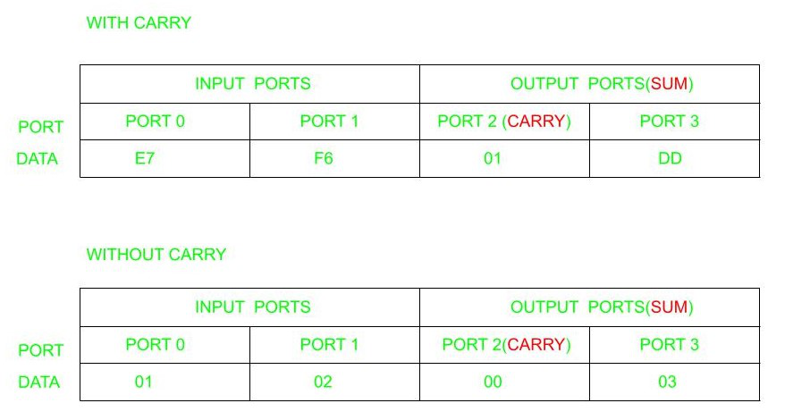
Problem: To write an assembly language program to add two 8 bit numbers in 8051 microcontroller using ports.
Example:
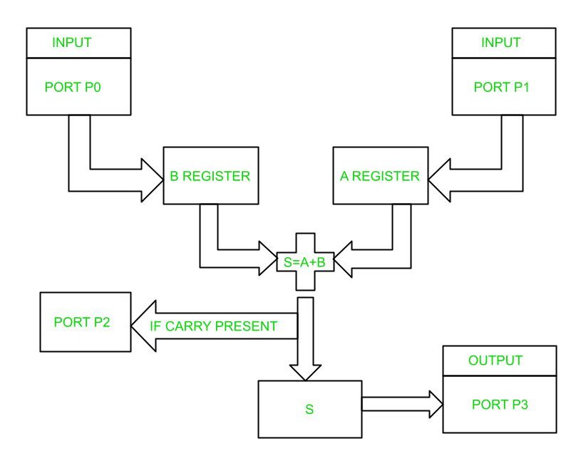
Block diagram:
Algorithm:
- Initialize Ports P0 and P1 as input ports.
- Initialize Ports P2 and P3 as output ports.
- Initialize the R1 register.
- Move the contents from Port 0 to B register.
- Move the contents from Port 1 to A register.
- Add contents in A and B.
- If carry is present increment R1.
- Move contents in R1 to Port 2.
- Move the sum in step 6 to Port 3.
Program:
ORG 00H                   // Indicates starting address

MOV P0,#0FFH              // Initializes P0 as input port
MOV P1,#0FFH              // Initializes P1 as input port
MOV P2,#00H               // Initializes P2 as output port
MOV P3,#00H               // Initializes P3 as output port

L1:MOV R1, #00H          // Initializes Register R1
MOV B,P0                 // Moves content of P0 to B
MOV A,P1                 // Moves content of P1 to A
CLR C                    // Clears carry flag
ADD A,B                  // Add the content of A and B and store result in A
JNC L2                   // If carry is not set, jump to label L2
INC R1                   // Increment Register R1 if carry present

L2: MOV P2, R1            // Moves the content from Register R1 to Port2
MOV P3,A                 // Moves the content from A to Port3
SJMP L1                  // Jumps to label L1
END
Explanation:
- ORG 00H is the starting address of the program.
- Giving the values as #0FFH and #00H initializes the ports as input and output ports respectively.
- R1 register is initialized to 0 so as to store any carry produced during the sum.
- MOV B, P0 moves the value present in P0 to the B register.
- MOV A, P1 moves the value present in P1 to Accumulator.
- ADD AB adds the values present in Accumulator and B register and stores the result in Accumulator.
- JNC L2 refers to jump to label L2 if no carry is present by automatically checking whether the carry bit is set or not.
- If the carry bit is set to increment register R1.
- MOV P2, R1, and MOV P3, A refers to moving the carry bit to P2 and result in Accumulator to P3.
Like Article
Suggest improvement
Share your thoughts in the comments
Please Login to comment...