8259 PIC Microcontroller
Last Updated :
06 May, 2023
Intel 8259 is a Programmable Interrupt Controller (PIC). There are 5 hardware interrupts and 2 hardware interrupts in Intel 8085 and Intel 8086 microprocessors respectively. But by connecting Intel 8259 with these microprocessors, we can increase their interrupt handling capability. Intel 8259 combines the multi-interrupt input sources into a single interrupt output. Interfacing of single PIC provides 8 interrupts inputs from IR0-IR7. For example, Interfacing of 8085 and 8259 increases the interrupt handling capability of 8085 microprocessor from 5 to 8 interrupt levels.
Features of Intel 8259 PIC are as follows:
- Intel 8259 is designed for Intel 8085 and Intel 8086 microprocessor.
- It can be programmed either in level triggered or in edge triggered interrupt level.
- We can mask individual bits of interrupt request register.
- We can increase interrupt handling capability upto 64 interrupt level by cascading further 8259 PICs.
- Clock cycle is not required.
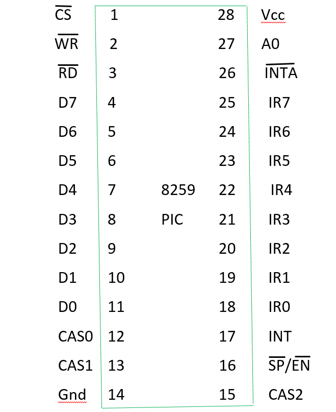
Pin Diagram of 8259 – We can see through above diagram that there are total 28 pins in Intel 8259 PIC where Vcc : 5V Power supply and Gnd : ground. Other pins use are explained below. Block Diagram of 8259 PIC microprocessor – 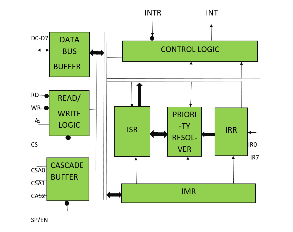 The Block Diagram consists of 8 blocks which are – Data Bus Buffer, Read/Write Logic, Cascade Buffer Comparator, Control Logic, Priority Resolver and 3 registers- ISR, IRR, IMR.
- Data bus buffer – This Block is used as a mediator between 8259 and 8085/8086 microprocessor by acting as a buffer. It takes the control word from the 8085 (let say) microprocessor and transfer it to the control logic of 8259 microprocessor. After selection of Interrupt by 8259 microprocessor (based on priority of the interrupt), it transfer the opcode of the selected Interrupt and address of the Interrupt service sub routine to the other connected microprocessor. The data bus buffer consists of 8 bits represented as D0-D7 in the block diagram. Thus, shows that a maximum of 8 bits data can be transferred at a time.
- Read/Write logic – This block works only when the value of pin CS is low (as this pin is active low). This block is responsible for the flow of data depending upon the inputs of RD and WR. These two pins are active low pins used for read and write operations.
- Control logic – It is the center of the PIC and controls the functioning of every block. It has pin INTR which is connected with other microprocessor for taking interrupt request and pin INT for giving the output. If 8259 is enabled, and the other microprocessor Interrupt flag is high then this causes the value of the output INT pin high and in this way 8259 responds to the request made by other microprocessor.
- Interrupt request register (IRR) – It stores all the interrupt level which are requesting for Interrupt services.
- Interrupt service register (ISR) – It stores the interrupt level which are currently being executed.
- Interrupt mask register (IMR) – It stores the interrupt level which have to be masked by storing the masking bits of the interrupt level.
- Priority resolver – It examines all the three registers and set the priority of interrupts and according to the priority of the interrupts, interrupt with highest priority is set in ISR register. Also, it reset the interrupt level which is already been serviced in IRR.
- Cascade buffer – To increase the Interrupt handling capability, we can further cascade more number of pins by using cascade buffer. So, during increment of interrupt capability, CSA lines are used to control multiple interrupt structure.
SP/EN (Slave program/Enable buffer) pin is when set to high, works in master mode else in slave mode. In Non Buffered mode, SP/EN pin is used to specify whether 8259 work as master or slave and in Buffered mode, SP/EN pin is used as an output to enable data bus.
Advantages:
Interrupt Management: The 8259 PIC is designed to handle interrupts efficiently and effectively, allowing for faster and more reliable processing of interrupts in a system.
Flexibility: The 8259 PIC is programmable, meaning that it can be customized to suit the specific needs of a given system, including the number and type of interrupts that need to be managed.
Compatibility: The 8259 PIC is compatible with a wide range of microprocessors, making it a popular choice for managing interrupts in many different systems.
Multiple Interrupt Inputs: The 8259 PIC can manage up to 8 interrupt inputs, allowing for the management of complex systems with multiple devices.
Ease of Use: The 8259 PIC includes simple interface pins and registers, making it relatively easy to use and program.
Disadvantages:
Cost: While the 8259 PIC is relatively affordable, it does add cost to a system, particularly if multiple PICs are required.
Limited Number of Interrupts: The 8259 PIC can manage up to 8 interrupt inputs, which may be insufficient for some applications.
Complex Programming: Although the interface pins and registers of the 8259 PIC are relatively simple, programming the 8259 can be complex, requiring careful attention to interrupt prioritization and other parameters.
Limited Functionality: While the 8259 PIC is a useful peripheral for interrupt management, it does not include more advanced features, such as DMA (direct memory access) or advanced error correction.
Like Article
Suggest improvement
Share your thoughts in the comments
Please Login to comment...